47
VC-G20SM/G200SM
VC-G201SM/G401SM
YES
YES
YES
NO
NO
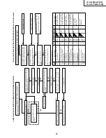
Check line between pins(79) and (78) of IC201.
Is there luminance signal (approx. 200mVp-p)
Check V-H.SW.P. line.
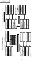
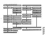
FLOW CHART NO.20 PLAYBACK MODE TROUBLESHOOTING
Playback picture does not appear. (E-E mode is possible)
Is the supply V-H. SW.P. signal fed to pin
(81) of IC201?.
Is there luminance signal input output
at pins (13) and (14) of IC201?.
Is there luminance signal (approx. 0.5Vp-p)
input output at pin (19) of IC201?.
Is there luminance signal (approx. 0.3Vp-p)
input output at pins (42) of IC201?.
Is there luminance signal (approx. 0.5Vp-p)
input output at pins (26) of IC201?.
Check peripheral circuit of pins (13) and (14)
of IC201?.
Check line between pins (18) and (19)
of IC201.
Check line between pins (21) and (42)
of IC201. (C208)
Check line between pins (39) and (26)
of IC201. (C212)
Is there luminance signal (approx. 0.5Vp-p)
input output at pin (39) of IC201?.
Is there luminance signal (approx. 0.5Vp-p)
inputted at pins (23) of IC201?.
Is voltage 5V applied to the CCD section power terminal at pin (36) of IC201?.
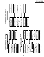
Although picture playback picture is possible, colour does not appear in PAL mode.(E-E mode is possible)
Is voltage of 5V applied to the chroma power
terminal pin(61) of IC201?
Is there chroma signal (approx. 156mVp-p/
burst) inputted at pin (46) of IC201?.
Is there chroma signal (approx. 197mVp-p/
bust) inputted at pin (58) of IC201?.
YES
YES
YES
Is there luminance signal (approx. 0.5Vp-p)
outputted at pins (52) of IC201?.
Check line between circuit of pins (24)and(23)
of IC201. (C210).
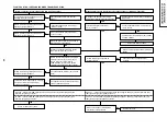
See FLOW CHART NO.18 E-E MODE TROUBLESHOOTING..
YES
YES
YES
YES
YES
YES
YES
NO
NO
NO
NO
NO
Replace IC201.
NO
Check peripherial circuit pin (61) of IC201 and
PC 5V line
Check line between pin (60)and pin (46)
of IC201.(C512).
NO
Check whether the pins (73) and (75)of IC201
oscillate 4.43MHz at PAL/SECAM mode.
Check parts around of X502.
Check line between circuit of pins (58)and
(35) of IC201.
Is there chroma signal (approx. 197mVp-p/
burst) outputted at pin (35) of IC201?.
Is there chroma signal (approx. 300mVp-p)
outputted at pin (55) of IC201?.
Is there chroma signal (approx. 300mVp-p/
bust) inputted at pin (54) of IC201?.
Check line between circuit of pins (55)and
(54) of IC201.
Replace IC201
YES
NO
YES
YES
YES
YES
YES
YES
YES
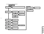
Is CCD control voltage approx. 5V applied normally to the pin (37) from pin (57) of IC201?
Is clock signal (approx. 8.86MHz/0.5Vp-p) for CCD applied normally to the pin (44) from (69) of IC201?
NO
Is there FM signal (approx. 200mVp-p)
inputted at pin(78) of IC201?
outputted at pin(78) of IC201?
Summary of Contents for VC-G200SM
Page 103: ...103 VC G20SM G200SM VC G201SM G401SM ...
Page 104: ...104 VC G20SM G200SM VC G201SM G401SM SIGNAL FLOW BLOCK DIAGRAM SIGNALVERLAUF BLOCKSCHALTBILD ...
Page 113: ...113 10 11 12 13 14 15 16 17 18 19 VC G20SM G200SM VC G201SM G401SM ...
Page 115: ...115 10 11 12 13 14 15 16 17 18 19 VC G20SM G200SM VC G201SM G401SM ...
Page 117: ...117 10 11 12 13 14 15 16 17 18 19 VC G20SM G200SM VC G201SM G401SM ...
Page 119: ...119 10 11 12 13 14 15 16 17 18 19 VC G20SM G200SM VC G201SM G401SM ...
Page 123: ...123 10 11 12 13 14 15 16 17 18 19 VC G20SM G200SM VC G201SM G401SM ...
Page 125: ...125 10 11 12 13 14 15 16 17 18 19 VC G20SM G200SM VC G201SM G401SM ...
Page 127: ...127 10 11 12 13 14 15 16 17 18 19 VC G20SM G200SM VC G201SM G401SM ...


