background image

56

Ref. No.

Part No.

Description

Code

Ref. No.

Part No.

Description

Code

VC-H9888U

7

6

5

4

3

2

1

A

B

C

D

E

F

G

H

301

300

304

311

308

311

305

306

309

303

312

316

315

307

314

310

317

313

302

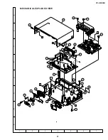
CASSETTE HOUSING CONTROL EXPLODED VIEW

Summary of Contents for VC-H9888U

Page 1: ...RES 5 1 2 SPECIFICATIONS 5 1 3 LOCATION OF MAJOR COMPONENTS AND CONTROL 6 2 DISASSEMBLY AND REASSEMBLY 7 2 1 DISASSEMBLY OF MAJOR BLOCKS 7 2 2 CARES WHEN REASSEMBLING 8 Page 3 ELECTRICAL ADJUSTMENT 9 4 TROUBLESHOOTING 12 5 BLOCK DIAGRAM 22 6 CIRCUIT DIAGRAM AND PWB FOIL PATTERN 32 7 REPLACEMENT PARTS LIST 45 8 EXPLODED VIEWS 55 9 PACKING OF THE SET 59 This document has been published to be used fo...

Page 2: ...ess to make certain that leads are not pinched or that hardware is not lodged between the chassis and other metal parts in the video cassette recorder 2 Inspect all protective devices such as non metallic control knobs insulation materials cabinet backs adjustment and compartment covers or shields isolation resistor capacitor networks mechanical insulators etc 3 To be sure that no shock hazard exi...

Page 3: ... courant de 120 volts Ne pas utiliser de transformateur d isolement pour cet essai Utiliser deux fils à pinces et connecter une résistance de 10 watts 1 5 kohm en parallèle avec un condensateur de 0 15 µF en série avec des pièces du coffret métallique exposées et une masse de terre connue telle qu un tuyau ou un conduit d eau Utiliser un VTVM ou VOM avec une sensibilité de 1000 ohms par volt ou pl...

Page 4: ...h the mechanism and its PWB in position in the main frame 1 Start and end sensors Q701 and Q702 Insert the sensor s projection deep into the upper hole of the holder Referring to the PWB fix the sensors tight enough 2 Photocoupler IC901 Refer to the symbol on the PWB and the anode marking of the part 3 Cam switches A and B D708 and D709 Adjust the notch of the part to the white marker of the symbo...

Page 5: ...o 45dB SP mode 3 Audio signal Input level 8dBs 309mVrms 47k ohm Output level 8dBs 309mVrms 1k ohm Frequency response 80Hz 10kHz SP mode linear 20Hz 20kHz Hi Fi mode Signal to noise ratio 43dB SP mode linear Hi Fi Dynamic range 90dB Hi Fi models Wow and flutter 0 005 max Hi Fi mode with T 120 tape 4 Receiving channel VHF Channels 2 13 UHF Channels 14 69 CATV Channels A 8 A 5 W 84 Antenna input Impe...

Page 6: ...VC H9888U 6 1 3 LOCATION OF MAJOR COMPONENTS AND CONTROL ...

Page 7: ...take out the front panel untilted OPERATION PWB Remove 1 clip a FRONT AV PWB Remove 2 screws 5 and 2 clip b JACK PWB JACK PWB HOLDER MECHANISM Undo the 3 hooks each of the front left hand and right hand PWB holders d and e Remove the 2 screws q and 9 each first and then the 2 screws 6 Undo the hooks f and c Take the mechanism the PWBs and the an tenna terminal board in this order out of the chassi...

Page 8: ...n the specified position This method is applied only for the mechanism INSTALLING THE MECHANISM ON PWB Lower vertically the mechanism paying attention to the mechanism edge and install the mechanism with due care so that the parts are not damaged So as to fix the mechanism to the main PWB install two housings Fit the antenna cover to one of them For other fix the vicinity of loading motor and sold...

Page 9: ...pleted The servo circuit adjustment data is written on the memory IC IC710 that is used in this product When this IC has been replaced it is necessary to readjust the servo circuit data Before readjusting this data warm up and age the set for more than 5 minutes Instruments required Color TV monitor Dual trace oscilloscope Alignment tape VROATSV VROABZGS Valve voltmeter 2 channel type TV signal ge...

Page 10: ...t back Commercial broadcast or video sig nal Color TV monitor Call up the test mode get TP802 short circuited Usethe TRACKING CHANNEL select and but tons of the set Sweep the noise bar down to the bottom of the colormonitor screen 1 Input commercial broadcast or video signal to video input terminal 2 Make recording on self recording tape in SP mode Play it back 3 Press the SLOW button and put the ...

Page 11: ...erator Sound multi plex signal generator and Valve volt meter 2 channel type E E mode Sound multiplex signal Audio output terminal L R R141 S IF ADJ Maximum difference in valve voltme ter pointer readings over 25 dB 1 Using the TV signal generator or the sound multiplex signal generator feed the sound multiplex signal to the set s antenna terminal 2 Set the sound multiplex signal generator to the ...

Page 12: ...e secondary rectifier circuits and rectifier diodes for short circuit D905 thru D909 D914 D916 thru D918 Q902 thru 903 IC904 etc FLOW CHART NO 5 TIMER TROUBLESHOOTING 1 The flourescent display tube fails light up Is the supply voltage of 5V fed to pin 18 of IC801 Check STBY 5V line Is the supply negative voltage of 24V fed to pin 16 of IC801 Check STBY 24V line Is there 4MHz oscillation at pins 19...

Page 13: ...rted Does pin 5 of IC705 change to about 10V when the cassette tape in inserted Does pin 2 of IC705 go to a H level about 1 7V when the cassette tape is inserted Does pin 79 of IC701 change from H to L level when the cassette tape is inserted Does the start sensor cover go to open when the cassette tape is inserted NO NO NO FLOW CHART NO 9 CASSETTE CONTROL TROUBLESHOOTING 2 A cassette tape is take...

Page 14: ...e voltage of Q951 change from about 5 0V to 4 5V Check line between Q952 and pin 94 of IC701 Is voltage of 5 0V sent out from the emitter of Q951 Check Q951 and STBY 15V line FLOW CHART NO 12 CAPSTAN MOTOR TROUBLESHOOTING The capstan motor fails to run Is the voltage more than about 2 6V DC given out of pin 32 of IC701 Check IC701 NO NO NO NO NO YES YES YES YES Is the supply voltage of 5V fed to p...

Page 15: ...ns 3 and 5 of AD c onnector and pins 66 and 65 Check line between AD ME harness and drum motor Are there drum PG and FG signals at pins 3 and 5 of IC701 respectively Check peripheral circuit of X701 NO YES In PB mode YES In PB mode Is there drum FG signal at pin 65 of IC701 present Is the V SYNC signal reference at pin 50 of IC701 YES YES NO NO Check peripheral circuit of C770 C771 and R770 Check ...

Page 16: ... line between rear video input terminal J202 and pin 30 of IC201 Check the line between front video input terminal J202 and pin 28 of IC201 2For U V tuner mode Check line between pin 24 of U V tuner and pin 31 of IC201 Is the supply voltage of 5V fed to pin 12 of IC201 YES YES YES Is there a picture signal outputted in the emitter of Q273 Check clump circuit Q273 Is there serial data and clock sig...

Page 17: ...IC201 Is CCD control voltage approx 5V normally to the pin 37 from pin 57 of IC201 Is clock signal approx 7 16MHz 0 5Vp p for CCD applied normally to the pin 44 from 69 of IC201 Although picture record is possible colour does not appear E E mode is possible NO NO NO YES YES Is voltage of 5V applied to the chroma power terminal at pin 61 of IC201 Check peripheral circuit pin 61 of IC201 and PC5V li...

Page 18: ...ma power terminal at pin 61 of IC201 YES Check peripheral circuit of pins 61 of IC201 and PC5V line NO Is there chroma signal approx 403mVp p burst at the pin 46 of IC201 YES NO Is there chroma signal approx 508mVp p burst at the pin 58 of IC201 Check line between pins 58 and 35 of IC201 R505 C515 YES YES NO Is there chroma signal approx 286mVp p burst output from the pin 55 of IC201 Replace IC201...

Page 19: ...ere audio signal outputted at pins 5 45 of IC651 Check line between pins 31 32 of IC651 and pins 17 18 of IC701 Check line between pins 4 5 and 46 45 of IC651 C651 C661 Are there serial data and clock at pins 31 and 32 of IC651 Replace IC651 Is pin 99 of IC201 L level No Hi Fi E E sound heard NO YES YES YES NO NO FLOW CHART NO 22 Hi Fi SOUND MODE TROUBLESHOOTING 2 Is there 600mVp p recording FM si...

Page 20: ...imposed with the bias signal at pin 4 of IC201 YES Check the MH AM harness and A C head YES NO NO NO FLOW CHART NO 25 LINEAR SOUND MODE TROUBLESHOOTING 2 YES YES Is theA C Head Clean Is the azimuth hight of A C head properly adjusted Replace A C head Is there a audio signal at pin 11 of IC201 YES Are the MH AA harness and the PB AMP peripheral parts normal Readjust A C Head hight YES No linear sou...

Page 21: ...VC H9888U 21 MEMO ...

Page 22: ...VC H9888U 22 7 6 5 4 3 2 1 A B C D E F G H VOLTAGE MEASUREMENT MODE PB Parentheses REC Without Parentheses 5 BLOCK DIAGRAMS SERVO BLOCK DIAGRAM ...

Page 23: ...VC H9888U 23 13 12 11 10 9 8 7 ...

Page 24: ...VC H9888U 24 7 6 5 4 3 2 1 A B C D E F G H VOLTAGE MEASUREMENT MODE PB Parentheses REC Without Parentheses SIGNAL FLOW BLOCK DIAGRAM PB Lum REC Lu ...

Page 25: ...VC H9888U 25 13 12 11 10 9 8 7 E E Signal Audio E E Signal Audio Playback Signal Audio Record Signal PB Chrominance Signal REC Chrominance Signal PB Luminance Signal REC Luminance Signal ...

Page 26: ...VC H9888U 26 7 6 5 4 3 2 1 A B C D E F G H VOLTAGE MEASUREMENT MODE PB Parentheses REC Without Parentheses GAMMA BLOCK DIAGRAM ...

Page 27: ...VC H9888U 27 13 12 11 10 9 8 7 ...

Page 28: ...VC H9888U 28 7 6 5 4 3 2 1 A B C D E F G H VOLTAGE MEASUREMENT MODE PB Parentheses REC Without Parentheses POWER CIRCUIT BLOCK DIAGRAM ...

Page 29: ...VC H9888U 29 13 12 11 10 9 8 7 ...

Page 30: ...VC H9888U 30 7 6 5 4 3 2 1 A B C D E F G H VOLTAGE MEASUREMENT MODE PB Parentheses REC Without Parentheses ...

Page 31: ...lowing diagram are measured with an SSVM upon receiving color bars 400 Hz sound signal in either the record mode or the play mode voltage is indi cated as follows 4 0 Record mode SP 4 0 PB mode SP 4 0 LP mode 4 0 EP mode NOTE 1 The unit of resistance ohm is omitted K 1000 ohms M 1 Meg ohm 2 All resistors are 1 8 watt unless otherwise noted 3 All capacitorsµF unless otherwise noted P µµF Voltages a...

Page 32: ...VC H9888U 32 7 6 5 4 3 2 1 A B C D E F G H VOLTAGE MEASUREMENT MODE PB Parentheses REC Without Parentheses 9 CIRCUIT DIAGRAM AND PWB FOIL PATTERN MAIN CIRCUIT 1 ...

Page 33: ...VC H9888U 33 13 12 11 10 9 8 7 ...

Page 34: ...VC H9888U 34 7 6 5 4 3 2 1 A B C D E F G H VOLTAGE MEASUREMENT MODE PB Parentheses REC Without Parentheses MAIN CIRCUIT 2 ...

Page 35: ...VC H9888U 35 13 12 11 10 9 8 7 ...

Page 36: ...VC H9888U 36 7 6 5 4 3 2 1 A B C D E F G H VOLTAGE MEASUREMENT MODE PB Parentheses REC Without Parentheses MAIN CIRCUIT 3 ...

Page 37: ...VC H9888U 37 13 12 11 10 9 8 7 ...

Page 38: ...VC H9888U 38 7 6 5 4 3 2 1 A B C D E F G H VOLTAGE MEASUREMENT MODE PB Parentheses REC Without Parentheses MAIN CIRCUIT 4 ...

Page 39: ...VC H9888U 39 13 12 11 10 9 8 7 ...

Page 40: ...VC H9888U 40 7 6 5 4 3 2 1 A B C D E F G H VOLTAGE MEASUREMENT MODE PB Parentheses REC Without Parentheses GAMMA CIRCUIT ...

Page 41: ...VC H9888U 41 13 12 11 10 9 8 7 ...

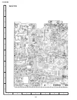
Page 42: ...VC H9888U 42 7 6 5 4 3 2 1 A B C D E F G H VOLTAGE MEASUREMENT MODE PB Parentheses REC Without Parentheses MAIN PWB ...

Page 43: ...VC H9888U 43 13 12 11 10 9 8 7 ...
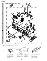
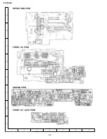
Page 44: ...VC H9888U 44 7 6 5 4 3 2 1 A B C D E F G H VOLTAGE MEASUREMENT MODE PB Parentheses REC Without Parentheses OPERATION PWB FRONT AV PWB GAMMA PWB FRONT AV JACK PWB ...

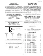
Page 45: ...curité que la pièce recommandée par l usine et repérée dans ce manuel de service peut provoquer une électrocution un incendie ou tout autre sinstre COMMENT COMMANDER LES PIECES DE RECHANGE Pour que votre commande soit rapidement et correctement remplie veuillez fournir les renseignements suivaints 1 NUMERO DU MODELE 2 NO DEREF 3 NO DE PIECE 4 DESCRIPTION MARK SPARE PARTS DELIVERY SECTION PRINTED W...

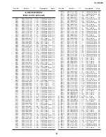
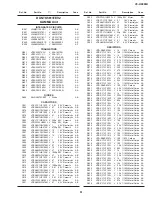
Page 46: ...4 1 V RL1N4004 AD D966 VHDRL1N4004 1 V RL1N4004 AD D967 VHDRL1N4004 1 V RL1N4004 AD D991 RH EX0631GEZZ V Zener Diode AA D992 RH DX0475CEZZ V Diode AB å IC901 RH FX0034CEZZ V PC817 AE Q701 RH PX0233GEZZ V PT493FL2 AD Q702 RH PX0233GEZZ V PT493FL2 AD PACKAGED CIRCUITS X501 RCRSB0204GEZZ V Crystal AG X701 RCRSB0156GEZZ V Crystal AF X702 RCRSB0138GEZZ V Crystal AD COILS AND TRANSFORMERS FL801 RFiLC009...

Page 47: ...5M V 3 3 50V Electrolytic AB C518 VCKYCY1HF333Z V 0 033 50V Ceramic AA C521 VCKYCY1HF103Z V 0 01 50V Ceramic AA C522 VCKYD41CY103N V 0 01 16V Ceramic AA C523 VCKYD41CY103N V 0 01 16V Ceramic AA C601 VCEA9M0JW107M V 100 6 3V Electrolytic AB C602 VCKYCY1EB103K V 0 01 25V Ceramic AA C603 VCEA9A0JW226M V 22 6 3V Electrolytic AB C604 VCKYCY1HB821K V 820p 50V Ceramic AA C605 VCEA9M1CW106M V 10 16V Elect...

Page 48: ... Metal Oxide AA R109 VRS CY1JF561J V 560 1 16W Metal Oxide AA R110 VRS CY1JF153J V 15k 1 16W Metal Oxide AA R111 VRS CY1JF153J V 15k 1 16W Metal Oxide AA R166 VRS CY1JF105J V 1M 1 16W Metal Oxide AA R167 VRS CY1JF104J V 100k 1 16W Metal Oxide AA R168 VRS CY1JF183J V 18k 1 16W Metal Oxide AA R169 VRS CY1JF103F V 10k 1 16W Metal Oxide AA R170 VRS CY1JF104J V 100k 1 16W Metal Oxide AA R171 VRS CY1JF2...

Page 49: ...JF393J V 39k 1 16W Metal Oxide AA R736 VRS CY1JF183J V 18k 1 16W Metal Oxide AA R737 VRS CY1JF102J V 1k 1 16W Metal Oxide AA R738 VRD RA2BE104J V 100k 1 8W Carbon AA R739 VRD RA2BE271J V 270 1 8W Carbon AA R740 VRS CY1JF104J V 100k 1 16W Metal Oxide AA R741 VRD RA2BE271J V 270 1 8W Carbon AA R742 VRS CY1JF154J V 150k 1 16W Metal Oxide AA R743 VRD RA2BE102J V 1k 1 8W Carbon AA R744 VRS CY1JF154J V ...

Page 50: ...lug 2pin TEST AB SC301 QSOCN0911REN1 V Socket 9pin AH AD SC601 QSOCN0604REN1 V Socket 6pin AA AB SC602 QSOCZ0293GEZZ V Socket 2pin AE AC SC701 QSOCN0704REN1 V Socket 7pin AD AB SC702 QSOCZ0292GEZZ V Socket 2pin AL AC SC703 QSOCZ1425CEZZ V Socket 14pin AF AD SC704 QSOCZ0625CEZZ V Socket 6pin AO AC SC705 QSOCN0506REN1 V Socket 5pin AJ AC S101 QSW S0004AJZZ V Switch RF Conv AF S701 QSW F0042AJZZ V Re...

Page 51: ...ytic AB C432 VCEA9M1CW106M V 10 16V Electrolytic AB C433 VCCCCY1HH330J V 33p 50V Ceramic AA C437 VCEA9M0JW476M V 47 6 3V Electrolytic AB C438 VCKYCY1CF104Z V 0 1 16V Ceramic AA C551 VCKYCY1CF104Z V 0 1 16V Ceramic AA C552 VCEA9M0JW476M V 47 6 3V Electrolytic AB RESISTORS R261 VRD RA2BE102J V 1k 1 8W Carbon AA R262 VRS CY1JF101J V 100 1 16W Metal Oxide AA R263 VRS CY1JF102J V 1k 1 16W Metal Oxide A...

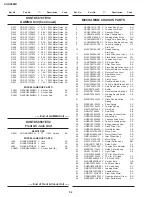
Page 52: ...LEVF0523AJZZ V Tension Arm Ass y AH 16 LANGF9620AJFW V A C Head Plate AG 17 MLEVP0271AJZZ V Sifter Drive Lever AE 18 MLEVP0272AJZZ V Pinch Double Action Lever AD 19 MLEVP0301AJZZ V Reverse Guide Lever Ass y AL 20 MLEVP0275AJZZ V Reverse Drive Lever AD 21 MLEVP0292AJZZ V Slow Brake Lever AE 22 MLEVP0290AJZZ V Open Lever AD 23 MLEVP0293AJZZ V Clutch Lever AE 24 MLEVP0294AJZZ V Sup Main Brake Ass y A...

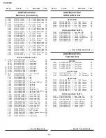
Page 53: ...1 5 2 0 8 AC SCREW NUTS AND WASHERS End of Mechanism Chassis Parts CASSETTE HOUSING CONTROL PARTS End of Cassette Housing Control Parts 66 XBPSD26P05J00 V Drum Drive Motor AA Mounting Screw SW2 6P 5S 67 PGiDC0056GEFW J Drum Base AL 68 QPWBF5468AJZZ V PWB LDG Motor AE 69 QPLGZ0292GEZZ J Socket LDG Motor AE 70 MSPRC0223AJFJ V Azimuth Spring AC 71 MSPRC0224AJFJ V Height Adjusting Spring AC MECHANISM ...

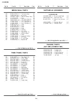
Page 54: ...0 V Screw AB 612 XJPSD30P10WS0 V Screw AA 613 PGUMS0026AJZZ V Foot Felt AB 614 PSLDM4551AJFW V H A Shield AE 615 LHLDZ2054AJZZ V Display Holder T AF 616 LHLDZ2055AJZZ V C B LED Holder AD 617 LX HZ3087GEFN J Screw AB 618 LHLDZ1962AJ00 V Sensor LED Holder AD 619 LHLDP1089AJ00 V LED Holder AC 620 LHLDZ2056AJZZ V AV Jack Holder AE 621 TLABM3913AJZZ V Model Lable AC End of Front Panel Parts FRONT PANEL...

Page 55: ... 19 29 49 51 8 11 203 49 51 7 58 52 4 25 24 2 33 15 1 50 218 207 67 207 53 216 41 61 21 38 17 208 60 47 44 6 30 36 9 39 45 219 10 30 40 27 43 46 43 35 35 37 34 23 48 209 210 211 212 213 223 5 26 32 68 69 22 55 16 202 222 221 201 202 202 220 59 70 57 71 56 63 62 66 66 66 66 65 8 EXPLODED VIEW MECHANISM CHASSIS EXPLODED VIEW ...

Page 56: ...Part No Description Code Ref No Part No Description Code VC H9888U 7 6 5 4 3 2 1 A B C D E F G H 301 300 304 311 308 311 305 306 309 303 312 316 315 307 314 310 317 313 302 CASSETTE HOUSING CONTROL EXPLODED VIEW ...

Page 57: ...Code Ref No Part No Description Code VC H9888U 7 6 5 4 3 2 1 A B C D E F G H B 603 603 616 610 611 609 610 615 605 609 604 601 612 606 607 618 A B A C D 617 621 620 C 613 D1 D1 600 609 614 602 609 609 619 D MECHANICAL EXPLODED VIEW ...

Page 58: ...sure that the cassette cover open le ver is between the front panel and the cassette cover Now fix the front panel in place Before attaching the front panel in position make surethatthecassettecover open lever is in its right place lower most If it is outofposition pushitdown with a finger Cassette cover Cassette cover open lever Cassette housing Cassette cover open lever Cassette cover open lever...

Page 59: ...onv CH preset at 3 channel Accessories TiNS 3487AJZZ Operation Manual TCADH0047AJZZ Operation Guide SSAKA0001AJZZ Polyethylene Sack RRMCG0287AJSA Infrared R C Unit SPAKX1018AJZZ Packing Foam SPAKC3931AJZZ Packing Case TLABK0005AJZZ Number Card Batteries SPAKP0030AJZZ Polyethylene Bag QCNW 0298AJZZ 75ohm Coaxial Cable FRONT ...

Page 60: ... publication may be reproduced stored in a retrieval system or transmitted in any form or by any means electronic mechanical photocopying recording or otherwise without prior written permission of the publisher TQ0568 S Dec 1998 Printed in Japan NA KY SHARP CORPORATION AV Systems Group Quality Reliability Control Center Yaita Tochigi 329 2193 Japan ...

Reviews: