34
VC-S101U
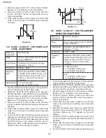
3. Press the numeric button "2" on the remote controller.
(Make sure "Y:2" appears on the set's display.)
4. Press the CH UP(+) or DN(-) button on the set or the
remote controller until the sub-emphasis level be-
comes as specified.
5. Finally take the above step 2 again to quit the test
mode. (You don't have to hold them down 2 seconds
or longer.)
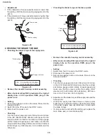
400mVp-p
Figure 5-4.
5-8 S-VHS / S-VHS ET / VHS WHITE CLIP
LEVEL ADJUSTMENT
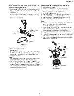
point
Measuring
Oscillosccope
instrument
Mode
REC (S-VHS/VHS/S-VHS ET SP/EP
mode), DNR-OFF
Input Signal
Standard color bar signal (S input
terminal), 1.0 Vp-p
Test point
TP402 ~ GND
Adjusting
Hold down the STOP button (S885)
and SET button (S802) at once, and
adjust the level using the CH (+)/(-)
buttons on the set or the remote
controller.
Specification
110
±
5% (S-VHS)
90
±
5% (S-VHS ET/VHS)
1. Feed the standard color bar signal (1.0 Vp-p) via the S
input terminal to call up the S-VHS mode.
2. Hold down the STOP button (S885) on the operation
PWB and the SET button (S802) on the main PWB at
once for about 2 seconds to call up the test mode.
3. Press the numeric button "3" on the remote controller.
(Make sure "Y:3" appears on the set's display.)
4. Press the CH UP(+) or DN(-) button on the set or the
remote controller until the white clip level becomes as
specified.
5. Finally take the above step 2 again to quit the test
mode. (You don't have to hold them down 2 seconds
or longer.)
6. For the S-VHS ET and VHS modes too, take the same
adjustment procedure as for the S-VHS mode. For the
S-VHS ET mode, insert a VHS cassette and turn on the
S-VHS ET button on the remote controller. For the
VHS mode, insert a VHS cassette and turn off the S-
VHS ET button on the remote controller.
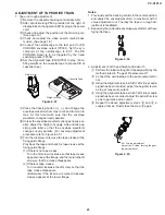
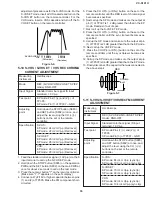
100%
Sync-tip
100% White
White clip level
Figure 5-5.
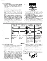
Measuring
Spectrum analyser
instrument
Mode
REC (S-VHS/VHS/S-VHS ET SP/EP
mode), DNR-OFF
Input Signal
Standard color bar signal (S input
terminal), 1.0 Vp-p
Test point
TP203 ~ GND
Adjusting
Hold down the STOP button (S885)
and SET button (S802) at once, and
adjust the level using the CH (+)/(-)
buttons on the set or the remote
controller.
Specification
S-VHS/S-VHS ET:
5.4
±
0.05 MHz (FM Carrier)
7.0
±
0.05 MHz (Deviation)
VHS:
3.4
±
0.05 MHz (FM Carrier)
4.4
±
0.05 MHz (Deviation)
5-9 S-VHS / S-VHS ET / VHS FM CARRIER/
DEVIATION ADJUSTMENT
1. Feed the standard color bar signal (1.0 Vp-p) via the S
input terminal to call up the S-VHS mode.
2. Hold down the STOP button (S885) on the operation
PWB and the SET button (S802) on the main PWB at
once for about 2 seconds to call up the test mode.
3. Press the numeric button "4" on the remote controller.
(Make sure "Y:4" appears on the set's display.)
4. Press the CH UP(+) or DN(-) button on the set or the
remote controller until the FM carrier frequency be-
comes as specified.
5. Finally take the above step 2 again to quit the test
mode. (You don't have to hold them down 2 seconds
or longer.)
6. Next take the above step 2 again to adjust the FM
deviation. Press the numeric button "5" on the remote
controller. (Make sure "Y:5" appears on the set's
display.)
7. Press the CH UP(+) or DN(-) button on the set or the
remote controller until the FM deviation becomes as
specified .
8. Finally take the above step 2 again to quit the test
mode. (You don't have to hold them down 2 seconds
or longer.)
9. For the S-VHS ET and VHS modes too, take the same
point
Summary of Contents for VC-S101U
Page 6: ...VC S101U 6 1 3 LOCATION OF MAJOR COMPONENTS AND CONTROL ...
Page 58: ...58 VC S101U 8 BLOCK DIAGRAM SYSTEM SERVO BLOCK DIAGRAM ...
Page 59: ...59 VC S101U ...
Page 60: ...60 VC S101U SIGNAL FLOW BLOCK DIAGRAM REC Luminance signal REC Chrominance signal ...
Page 62: ...62 VC S101U AUDIO BLOCK DIAGRAM ...
Page 63: ...63 VC S101U REC Signal PB Signal EE Signal ...
Page 64: ...64 VC S101U POWER CIRCUIT BLOCK DIAGRAM ...
Page 67: ...67 13 12 11 10 9 8 7 VC S101U ...
Page 69: ...69 13 12 11 10 9 8 7 VC S101U ...
Page 71: ...71 13 12 11 10 9 8 7 VC S101U ...
Page 73: ...73 13 12 11 10 9 8 7 VC S101U ...
Page 75: ...75 13 12 11 10 9 8 7 VC S101U ...
Page 77: ...77 13 12 11 10 9 8 7 VC S101U ...
Page 79: ...79 13 12 11 10 9 8 7 VC S101U ...
Page 81: ...81 13 12 11 10 9 8 7 VC S101U ...
Page 83: ...83 13 12 11 10 9 8 7 VC S101U ...
Page 84: ...84 7 6 5 4 3 2 1 A B C D E F G H VC S101U PWB FOIL PATTERN MAIN PWB ...
Page 85: ...85 13 12 11 10 9 8 7 VC S101U ...
Page 86: ...86 7 6 5 4 3 2 1 A B C D E F G H VC S101U Y C PWB SIDE A Y C PWB SIDE B ...
Page 87: ...87 13 12 11 10 9 8 7 VC S101U NR PWB SIDE A NR PWB SIDE B ...
Page 88: ...88 7 6 5 4 3 2 1 A B C D E F G H VC S101U Hi Fi JACK PWB SIDE A SIDE B ...
Page 89: ...89 13 12 11 10 9 8 7 VC S101U OPERATION PWB FRONT A V PWB ...
Page 90: ...90 7 6 5 4 3 2 1 A B C D E F G H VC S101U JACK PWB SIDE A JACK PWB SIDE B ...

