VC-S101U
44
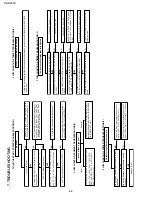
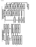
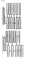
FLOW CHART NO.1 POWER TROUBLESHOOTING(1)
No power
Unplug the AC power cord. Replug it a few
seconds later.
YES
YES
YES
YES
NO
NO
NO
NO
NO
Is the fuse good?
Is AT 5V voltage line normal?
Check the secondary rectifier circuits.
Check the backup error voltage detection
circuit (Q704, Q705, Q711 and D721).
Is "H" level applied at pin(1) of IC701?
Check the primary circuit parts for leakage or
short-circuit. (L901, D921, T901, C904, C907
- 908,IC903, IC901, C918, D901, D903,D912
- 913,R906~908, R912~914, etc.)
Replace the fuse. If it blows out again, go to
FLOW CHART NO.2 (Fuse blows out).
Are PC 12V, PC 5V, PC 12V(2), AT 23V, AT
42V, AT 15V, AT-25V and filament voltage
lines normal?
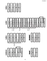
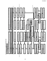
FLOW CHART NO.2 POWER TROUBLESHOOTING(2)
In case of fuse blown out.
Check
primary circuit for
short-circuit or leak.
(L901, T901, C904, IC903, IC901, C918,
C907-908, D901, D903, D910, D912-913,
D921, R912-914, etc.)
Check the secondary rectifier circuits and
rectifier diodes for short-circuit. (D906- D909,
D918, D926-927, etc.)
Case (1)
Case (2)
7. TROUBLESHOOTING
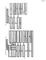
FLOW CHART NO.4 POWER TROUBLESHOOTING(3)
In case of abnormal noise(sound)
Check the secondary rectifier circuits and rectifier diodes for short-circuit. (D906 thru D909, D918,
IC904, etc.)
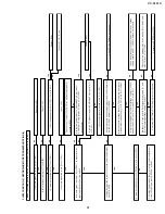
FLOW CHART NO.5 TIMER TROUBLESHOOTING (1)
The flourescent display tube fails light up.
Is the supply voltage of 5V fed to pin(18) of IC801?
Check AT 5V line.
Is the supply negative voltage of -25V fed to pin(16)
of IC801?
Check AT -25V line.
Is there 4MHz oscillation at pins(19) and (20) of
IC801?
Check FL801 and IC801.
Do IC701, IC801, as well as the FIP DATA, FIP
CLOCK and FIP CS signal lines function?
Check the FIP DATA, FIP CLOCK and
FIP CS signal lines between IC701 and
IC801.
Check the fluorescent display tube and its periph-
erals.
Check for cracks on the fluorescent
display tube.
YES
YES
YES
YES
YES
NO
NO
NO
NO
NO
Is the filament voltage applied between (16)/(17)
and (46)/(47) of the fluorescent display tube?
Check Q910,R916, D952 and R952
NO
YES
YES
NO
NO
FLOW CHART NO.3 POWER TROUBLESHOOTING(4)
Output voltage fluctuates too much.
Check the circuit and replace the defective
parts (IC901, IC902, R925-926, etc.).
Check the circuit and replace the defective
parts. (IC901, D913, T901,R913, C918 etc.)
Replace IC901.
Does the secondary photocoupler circuit
function?
Does the primary photocoupler circuit
function?
Summary of Contents for VC-S101U
Page 6: ...VC S101U 6 1 3 LOCATION OF MAJOR COMPONENTS AND CONTROL ...
Page 58: ...58 VC S101U 8 BLOCK DIAGRAM SYSTEM SERVO BLOCK DIAGRAM ...
Page 59: ...59 VC S101U ...
Page 60: ...60 VC S101U SIGNAL FLOW BLOCK DIAGRAM REC Luminance signal REC Chrominance signal ...
Page 62: ...62 VC S101U AUDIO BLOCK DIAGRAM ...
Page 63: ...63 VC S101U REC Signal PB Signal EE Signal ...
Page 64: ...64 VC S101U POWER CIRCUIT BLOCK DIAGRAM ...
Page 67: ...67 13 12 11 10 9 8 7 VC S101U ...
Page 69: ...69 13 12 11 10 9 8 7 VC S101U ...
Page 71: ...71 13 12 11 10 9 8 7 VC S101U ...
Page 73: ...73 13 12 11 10 9 8 7 VC S101U ...
Page 75: ...75 13 12 11 10 9 8 7 VC S101U ...
Page 77: ...77 13 12 11 10 9 8 7 VC S101U ...
Page 79: ...79 13 12 11 10 9 8 7 VC S101U ...
Page 81: ...81 13 12 11 10 9 8 7 VC S101U ...
Page 83: ...83 13 12 11 10 9 8 7 VC S101U ...
Page 84: ...84 7 6 5 4 3 2 1 A B C D E F G H VC S101U PWB FOIL PATTERN MAIN PWB ...
Page 85: ...85 13 12 11 10 9 8 7 VC S101U ...
Page 86: ...86 7 6 5 4 3 2 1 A B C D E F G H VC S101U Y C PWB SIDE A Y C PWB SIDE B ...
Page 87: ...87 13 12 11 10 9 8 7 VC S101U NR PWB SIDE A NR PWB SIDE B ...
Page 88: ...88 7 6 5 4 3 2 1 A B C D E F G H VC S101U Hi Fi JACK PWB SIDE A SIDE B ...
Page 89: ...89 13 12 11 10 9 8 7 VC S101U OPERATION PWB FRONT A V PWB ...
Page 90: ...90 7 6 5 4 3 2 1 A B C D E F G H VC S101U JACK PWB SIDE A JACK PWB SIDE B ...

