45
VC-S101U
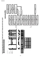
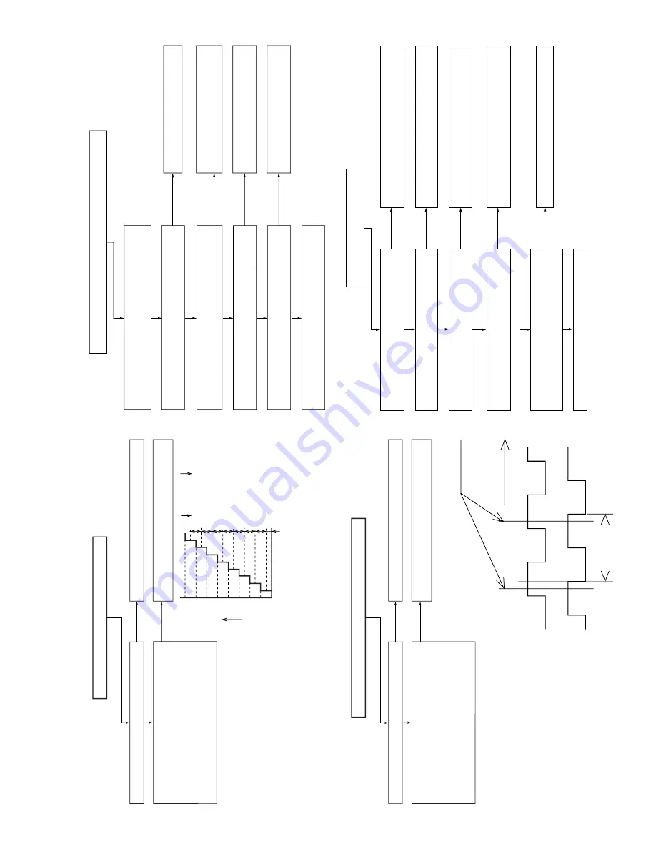
4.4V
3.8V
3.1V
2.5V
1.9V
1.2V
0.6V
0V
TP801
CASS. JP.
TP802
TEST
S802
SET
S801
CH SET
S882
CH(+)
S892
ET
S891
AV AUTO REC
KEY-0
S887
REC
S881
PLAY
S885
STOP
S884
PAUSE/STILL
S883
CH(-)
S894
EJECT
S893
POWER
KEY-1
KEY-0/KEY-1 INPUT VOLTAGE(V)
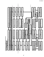
KEY OPERATION DOES NOT FUNCTION
Are the key switches well fit and functioning?
Do the KEY-0 and KEY-1 circuits from the
switches to pins (88) and (87) of IC701 func-
tion?
With a key pressed, is its specified voltage
applied to the KEY-0 and KEY-1 circuits up
to pins (88) and (87) of IC701?
Replace a defective key switch.
Check the KEY
-0 and KEY
-1 circuits and all
the switches.
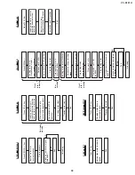
FLOW CHART NO.6 TIMER TROUBLESHOOTING (2)
YES
NO
NO
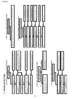
FLOW CHART NO.8 INFRARED R/C TROUBLESHOOTING
No operation is possible from the infrared remote control.
Operation is possible with the VCR set, but not with
the remote controller.
Check and /or replace infrared
remote control as required.
Is 5V voltage supplied to pin (1) on the remote
control receiver?
Check AT 5V and GND lines.
Is "L" pulse sent out from pin(3) of the receiver when
the infrared remote control is activated?
YES
YES
NO
NO
NO
YES
NO
YES
YES
Is pulse signal supplied to pin (5) of IC701?
Check line between receiver
and IC701.
Are the remote control 1/2 settings proper?
Make the same settings on the set
and the remote controller.
Replace IC701.
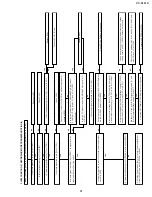
SHUTTLE RING OPERATION DOES NOT FUNCTION
Is the shuttle switche well fit and functioning?
Do the JOG-1 and JOG-2 circuits from the
shuttle switch to pins (8) and (9) of IC701
function?
With shuttle switch operated, is its specified
voltage applied to the JOG-1 and JOG-2
circuits up to pins (8) and (9) of IC701?
Replace a defective switch.
Check the JOG-1 and JOG-2 circuits and
the switch.
FLOW CHART NO.7 TIMER TROUBLESHOOTING (3)
YES
NO
NO
JOG-1
JOG-2
T
T = 30
°
(12 position)
click point
CW
YES
YES
YES
YES
NO
YES
NO
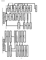
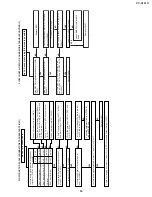
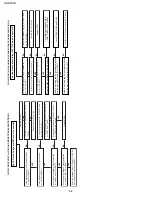
FLOW CHART NO.9 CASSETTE CONTROL TROUBLESHOOTING(1)
A cassette tape is not take in.
NO
NO
NO
Check start sensor cover.
Check line between start sensor and pin(79)
of IC701
Check line between pin(93) of IC703 and pin
(2) of IC705.
Check IC705.
Check line between IC705 and loading motor.
Replace loading motor.
Is the specified voltage ( about 10V)applied at
the loading motor terminal when the cassette
tape is inserted?
Does pin(5) of IC705 change to about 10V
when the cassette tape in inserted?
Does pin(2) of IC705 go to a "H" level (about
1.7V) when the cassette tape is inserted?
Does pin(79) of IC701 change from"H" to "L"
level when the cassette tape is inserted?
Does the start sensor cover go to open when
the cassette tape is inserted?
Summary of Contents for VC-S101U
Page 6: ...VC S101U 6 1 3 LOCATION OF MAJOR COMPONENTS AND CONTROL ...
Page 58: ...58 VC S101U 8 BLOCK DIAGRAM SYSTEM SERVO BLOCK DIAGRAM ...
Page 59: ...59 VC S101U ...
Page 60: ...60 VC S101U SIGNAL FLOW BLOCK DIAGRAM REC Luminance signal REC Chrominance signal ...
Page 62: ...62 VC S101U AUDIO BLOCK DIAGRAM ...
Page 63: ...63 VC S101U REC Signal PB Signal EE Signal ...
Page 64: ...64 VC S101U POWER CIRCUIT BLOCK DIAGRAM ...
Page 67: ...67 13 12 11 10 9 8 7 VC S101U ...
Page 69: ...69 13 12 11 10 9 8 7 VC S101U ...
Page 71: ...71 13 12 11 10 9 8 7 VC S101U ...
Page 73: ...73 13 12 11 10 9 8 7 VC S101U ...
Page 75: ...75 13 12 11 10 9 8 7 VC S101U ...
Page 77: ...77 13 12 11 10 9 8 7 VC S101U ...
Page 79: ...79 13 12 11 10 9 8 7 VC S101U ...
Page 81: ...81 13 12 11 10 9 8 7 VC S101U ...
Page 83: ...83 13 12 11 10 9 8 7 VC S101U ...
Page 84: ...84 7 6 5 4 3 2 1 A B C D E F G H VC S101U PWB FOIL PATTERN MAIN PWB ...
Page 85: ...85 13 12 11 10 9 8 7 VC S101U ...
Page 86: ...86 7 6 5 4 3 2 1 A B C D E F G H VC S101U Y C PWB SIDE A Y C PWB SIDE B ...
Page 87: ...87 13 12 11 10 9 8 7 VC S101U NR PWB SIDE A NR PWB SIDE B ...
Page 88: ...88 7 6 5 4 3 2 1 A B C D E F G H VC S101U Hi Fi JACK PWB SIDE A SIDE B ...
Page 89: ...89 13 12 11 10 9 8 7 VC S101U OPERATION PWB FRONT A V PWB ...
Page 90: ...90 7 6 5 4 3 2 1 A B C D E F G H VC S101U JACK PWB SIDE A JACK PWB SIDE B ...

