26
VL-NZ50S/H/E/W/NZ80H
VL-NZ100S/H/E
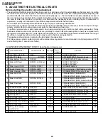
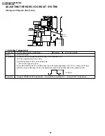
ADJUSTING THE VIDEO I/O CIRCUIT SYSTEM
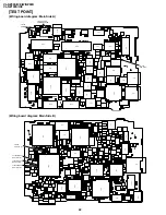
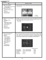
(Wiring board diagram: Main Side A)
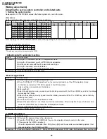
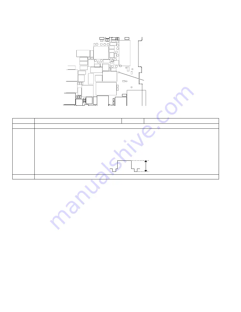
1. PCO D/A-Y adjustment
Test point
TL1479 (connected to oscilloscope)
Address
VCR ADJ 566/567
Mode
VCR STOP mode
Procedure
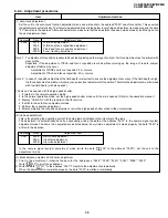
1) Connect the AVS cable and then connect it to the monitor (TO).
2) Call the adjustment mode (V-ADJ).
3) Set the address to "566", and call the date.
(100% white signal is output.)
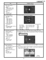
4) Vary the data with the FF and REW keys to set the signal appearing at TL1479 to 1.0Vp-p
±
0.05Vp-p.
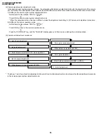
5) Write a value subtracting -6h from the adjustment data of the address 566h in the address 567h.
Examples
• During E
2
PROM(IC705) replacement. • During IC4401 replacement. • During IC1401 replacement.
1.0
±
0.05
R
5
C
5
C57
Q908
C971
FL5701
R5704
L916
R988
C973
Q907
R989
R5706
J5701
C980
R990
R996
FB5702
C974
L917
Q2903
R2919
TL1478
R2911
R950
R951
C992
VA1401
TL1472
Q2906
D2904
Q911
IC2901
C990
VA1402
TL1479
D2903
C2902
R2917
R1483
TL1470
C930
TL1471
Q2901
D2905
TL2902
TL2901
R2905
TL2903
R2907
CP1
Q2904
R2903
Q2902
TL906
D2901
R2901
TL905
TL904
R2904
R2902
CP2
R2906
R2918
D2902
Q2905
TL2904
R2913
D2906
SC900
P901
TL997
R2909
TL2906
R2908
TL2907
C901
D2908
TL902
TL901
TL900
TL903
C2903
TL2905
R913
R2910
R2858
R2857
R2860
C2901
R1480
FB2801
R2914
R2915
TL1479
PCO D/A-Y

