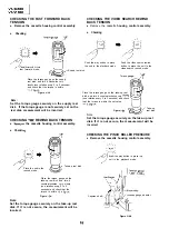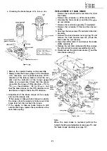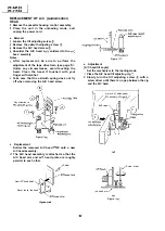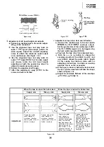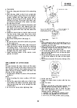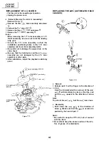
Detach the pinch roller from the capstan shaft.
Set the tension gauge by hooking the tension
gauge adapter onto the pinch roller shaft.
Gradually release the pressure to allow the pinch
roller to touch the capstan shaft. When the
pinch roller
just
touches the capstan shaft, read
the indication on the gauge.
Check that the reading of the tension gauge is in
the range of
to
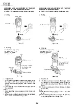
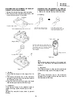
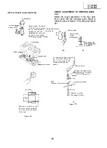
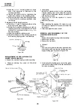
CHECKING AND ADJUSTMENT OF TENSION
POLE POSITION
l
Remove the cassette housing control assembly.
l
Setting
Place the unit in
the record mode.
Guide roller A
head
impedance.
roller
roller B
Check the left
side position
(by sight).
T
g
Tension
and plate
adjusting
jig
setting hole
l
Checking
Video Cassette tape (E-l
Figure
I. The guide rollers (A, operate to bring the tape
outside the cassette tape and simultaneously the
tension pole moves to the left, loading the tape.
At that time (loading completed), check the
position of the tension pole.
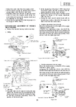
At the beginning of the tape
check that
the tension pole’s left side is aligned with the
supply impedance roller’s center by sight.
Check that the end of the tape is neither curled
against the flange of the supply impedance
roller nor over it.
During the video search rewind mode with no
cassette tape in place, check that the supply reel
disk is free from the tension band.
l
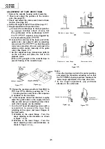
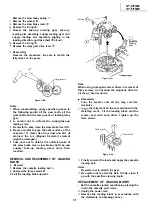
Position adjustment (record mode)
When the tension pole is at the right of the supply
impedance roller’s center:
the tightening screw, and shift the
tension band adjustment bracket in the direction of
the arrow using a tension band and plate adjusting
Jig until it is in the set value range (center). Then
secure it with the tightening screw.
Center
I
impedance
roller
Tension
pole
Tension band
and plate
adjusting jig
band adjustment bracket
Figure
l
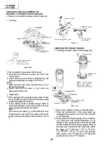
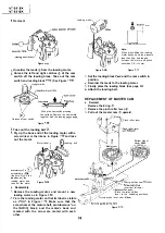
Position adjustment (record mode)
When the tension pole is at the left of the supply
impedance roller’s center:
the tightening screw, and shift the
tension band adjustment bracket in the direction of
the arrow using a tension band and plate adjusting
Jig until it is in the set value range (center). Then
secure it with the tightening screw.
I
I
Supply impedance
roller
T e n s i o n
pole
Tension band
and plate
adjusting jig
Tension
band adjustment
bracket
Figure
Summary of Contents for VT-3418X
Page 54: ...VT 341 8X VT 51 18X is z 0 Y Y c U T J 2 c 4 54 ...
Page 61: ...VT 341 8X VT 51 18X TROUBLESHOOTING OF TV SECTION I I I I 1 I I I I I I I ___ I iiE I b z 61 ...
Page 74: ...m 3418X i T 5118X VCJ AV UNIT 7 I 8 I 9 I 10 I 11 I 12 I 74 ...
Page 76: ...VT 341 8X VT 5118X VCJ AV UNIT I 7 I 8 I 9 I 10 I 11 I 12 1 76 ...
Page 78: ...PWB B V I D E O CHROMA J U N G L E 7 I 8 I 9 I 10 I 11 I 12 I 78 ...
Page 80: ...PWE 8 I 1 V I D E O CHROMA JUNGLE hr r I 7 I 8 I 9 I 10 I 11 I 12 I 80 ...
Page 86: ...VT 341 8X VT 5118X 7 I 8 I 9 I 10 I 11 I 12 I 86 ...
Page 88: ...rr J I I TUNER w2o1 m ...
Page 89: ...n 3 30 ...
Page 90: ...VT 341 8X VT 5118X VCJ AV UNIT DUNTK830 I WEV3 I I I m c I 7 I 8 I 9 I 10 1 11 I 12 I 90 ...
Page 92: ... VT 341 8X VT 51 18X DUNTK8302WEV 1 DUNTK8303WEV I I 7 I 8 I 9 I 10 I 11 I 12 I 92 ...
Page 94: ...VT 341 8X VT 5118X DUNTK8302WEV3 DUNTK8303WEV3 7 I 8 I 9 I 10 I 11 I 12 I 94 ...
Page 97: ... _ _ _ __ D I m I n I t3 I m I n I GI I I 1 ...
Page 98: ...Memo _ a _ _ 98 ...
Page 102: ...I REC I w r I I I CAPSTAN FG 7 I 8 I 9 I 10 I 11 I 12 1 102 ...
Page 106: ...CASSETTE SW REC TIP I ED M I I II DFfwPG I I I I I I I I I I I I ...
Page 110: ...VT 341 8X I VT 5118X 1 J 7 I 8 I 9 I 10 I 11 I 12 I 110 ...
Page 112: ...VT 341 8X I T 5118X 1 WAVEFORMS 112 ...
Page 115: ...SCHEMATIC DIAGRAM n VCR Main Unit r 7 I 1 I 2 I 3 I 4 I 5 I 6 115 ...
Page 119: ...D I c9 I n I u I m I n I GI I I I ...
Page 123: ...D I a I n I u I m I n I GI I I I ...
Page 124: ...11 I 12 I ...
Page 126: ...J l J I i _ _ _ ___ I _ _ n f f 7 I 8 I 9 I 10 I 11 I 12 126 ...
Page 152: ...VT 341 8X VT 5118X MECHANISM CHASSIS PARTS 152 ...
Page 155: ...H G F E D C B A CASSETTE HOUSING CONTROL PARTS 1 I 2 I 3 I 4 I 5 I 6 I 155 ...
Page 157: ...MECt 1 I 2 I 3 I 4 I 5 I 6 157 ...
Page 158: ...VT 341 8X VT 51 18X I I 7 I 8 I 9 I 10 I 11 I 12 I 158 ...
Page 161: ...H G F E D C B A VT 341 8X VT 5118X 1 2 I 3 I 4 I 5 I 6 161 ...
Page 162: ...VT 341 8X VT 51 18X I I 7 I 8 I 9 I 10 I 11 I 162 12 I ...
Page 163: ... 1 DEL VT 3418X CABINET AND MECHANICAL PARTS 0 II I L e e m I w F J 1 I 2 I 3 I 4 I 5 I 6 163 ...
Page 164: ... ...
Page 169: ...Memo m 169 ...
Page 170: ...S H A R P T98 19 S Printed in Japan 0 w s MW KD ...

