ADJUSTMENT
(Continued)
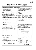
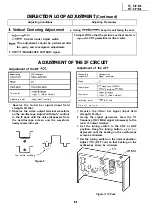
White Balance and Back Ground Adjustment
Adjusting Point
Green Drive control
Cl
Blue Drive control
Sub-Contrast control
Vote:
to this adjustment, warm up the unit with the
current of more than
I
for more than
minutes.
I. Receive “MONOSCOPE PATTERN” signal with
pattern generator.
Set the Contrast and Brightness controls at MAX
position.
Connect beam ammeter to
and
(Full scale: 3
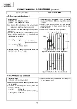
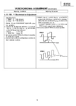
Sub-Tint Adjustment
Bell Filter Adjustment
Adjusting Point
Sub-Tint control
Feed
COLOUR BAR” signal to video in jack
with
bar generator at the
mode.
Connect oscilloscope to
Set the Tint control at the CENTER
position.
Set Service switch
at the Video Cut position
to cut off the Y-signal.
Adjusting Point
Bell Filter
Receive
COLOUR BAR” signal with
bar generator.
Connect oscilloscope to
with the
following settings.
l
Range:
div. AC
l
Sweep Time:
div.
l
Probe:
l/l 0
1
or more)
Adjust the Sub-Contrast control so that the beam
current becomes
1
(rough adjustment).
Adjust the Green Drive control and Blue Drive
control so that the
temperature is at
l
High beam:
Adjust the Contrast control and Brightness
control so that the beam current is
and check that the
temperature is
at
If the temperature is not at
go back to “CRT CUT-OFF ADJUSTMENT” and
repeat the adjustment.
=
Y =
Adjust
control key to obtain the output of
Adjust Sub-Tint control
so that the output
waveform is as shown in figure below.
Return
to CENTER (normal position).
Same
B - Y
level
.
W Y
R B
Adjust the Bell Filter
so that the red
output and blue
output will have the same
amplitude.
R
Same amplitude
9
Summary of Contents for VT-3418X
Page 54: ...VT 341 8X VT 51 18X is z 0 Y Y c U T J 2 c 4 54 ...
Page 61: ...VT 341 8X VT 51 18X TROUBLESHOOTING OF TV SECTION I I I I 1 I I I I I I I ___ I iiE I b z 61 ...
Page 74: ...m 3418X i T 5118X VCJ AV UNIT 7 I 8 I 9 I 10 I 11 I 12 I 74 ...
Page 76: ...VT 341 8X VT 5118X VCJ AV UNIT I 7 I 8 I 9 I 10 I 11 I 12 1 76 ...
Page 78: ...PWB B V I D E O CHROMA J U N G L E 7 I 8 I 9 I 10 I 11 I 12 I 78 ...
Page 80: ...PWE 8 I 1 V I D E O CHROMA JUNGLE hr r I 7 I 8 I 9 I 10 I 11 I 12 I 80 ...
Page 86: ...VT 341 8X VT 5118X 7 I 8 I 9 I 10 I 11 I 12 I 86 ...
Page 88: ...rr J I I TUNER w2o1 m ...
Page 89: ...n 3 30 ...
Page 90: ...VT 341 8X VT 5118X VCJ AV UNIT DUNTK830 I WEV3 I I I m c I 7 I 8 I 9 I 10 1 11 I 12 I 90 ...
Page 92: ... VT 341 8X VT 51 18X DUNTK8302WEV 1 DUNTK8303WEV I I 7 I 8 I 9 I 10 I 11 I 12 I 92 ...
Page 94: ...VT 341 8X VT 5118X DUNTK8302WEV3 DUNTK8303WEV3 7 I 8 I 9 I 10 I 11 I 12 I 94 ...
Page 97: ... _ _ _ __ D I m I n I t3 I m I n I GI I I 1 ...
Page 98: ...Memo _ a _ _ 98 ...
Page 102: ...I REC I w r I I I CAPSTAN FG 7 I 8 I 9 I 10 I 11 I 12 1 102 ...
Page 106: ...CASSETTE SW REC TIP I ED M I I II DFfwPG I I I I I I I I I I I I ...
Page 110: ...VT 341 8X I VT 5118X 1 J 7 I 8 I 9 I 10 I 11 I 12 I 110 ...
Page 112: ...VT 341 8X I T 5118X 1 WAVEFORMS 112 ...
Page 115: ...SCHEMATIC DIAGRAM n VCR Main Unit r 7 I 1 I 2 I 3 I 4 I 5 I 6 115 ...
Page 119: ...D I c9 I n I u I m I n I GI I I I ...
Page 123: ...D I a I n I u I m I n I GI I I I ...
Page 124: ...11 I 12 I ...
Page 126: ...J l J I i _ _ _ ___ I _ _ n f f 7 I 8 I 9 I 10 I 11 I 12 126 ...
Page 152: ...VT 341 8X VT 5118X MECHANISM CHASSIS PARTS 152 ...
Page 155: ...H G F E D C B A CASSETTE HOUSING CONTROL PARTS 1 I 2 I 3 I 4 I 5 I 6 I 155 ...
Page 157: ...MECt 1 I 2 I 3 I 4 I 5 I 6 157 ...
Page 158: ...VT 341 8X VT 51 18X I I 7 I 8 I 9 I 10 I 11 I 12 I 158 ...
Page 161: ...H G F E D C B A VT 341 8X VT 5118X 1 2 I 3 I 4 I 5 I 6 161 ...
Page 162: ...VT 341 8X VT 51 18X I I 7 I 8 I 9 I 10 I 11 I 162 12 I ...
Page 163: ... 1 DEL VT 3418X CABINET AND MECHANICAL PARTS 0 II I L e e m I w F J 1 I 2 I 3 I 4 I 5 I 6 163 ...
Page 164: ... ...
Page 169: ...Memo m 169 ...
Page 170: ...S H A R P T98 19 S Printed in Japan 0 w s MW KD ...


