I
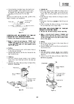
CHECKING THE BRAKE TORQUE
l
Checking the brake torque at the supply side
, Supply reel disk
l
the brake torque at the take-up
side
Figure
l
Remove the cassette housing control assembly.
l
Make a short-circuit between
and
both located at the center on your side
on the VCR
with a
ohm resistor. Now
turn on the power.
Setting
Set a torque
gauge to zero on the scale. Place it
on the supply reel disk.
Switch from the mode to the STOP mode.
Disconnect the AC power plug.
l
Checking
Slowly rotate the torque gauge in the clockwise
direction and counterclockwise
direction of the supply brake so that the reel disk
and the indicator of the torque gauge rotate at
an equal rate. Check that the values are within
the range of
direction
direction =
and that the brake torque in the
direction is at least twice as high as that in
the
direction.
Figure
l
Remove the cassette housing control assembly.
l
Make a short-circuit between
and
both located at the center on your side
on the VCR
with a
ohm resistor. Now
turn on the power.
Setting
Set a torque gauge to zero on the scale. Place it
on the take-up reel disk.
Switch from the mode to the STOP mode.
Disconnect the AC power plug.
l
Checking
Slowly rotate the torque gauge in the clockwise
direction and counterclockwise
direction of the take-up brake so that the reel
disk and the indicator of the torque gauge
rotate at an equal rate. Check that the values
are within the range of
direction=
direction =
and that the brake
torque in the
direction is at least twice as
high as that in the
direction.
l
Adjustment of the brake torque at the supply
side and the take-up side
If the supply or take-up brake torque is outside
the range, clean the supply or take-up reel disk
break lever pad, then recheck the torque.
If the supply or take-up brake torque is still
outside the range, replace the main brake
or the main brake spring.
Note:
When the main brake is replaced, perform the
height checking and adjustment of reel disks (see
page
and the brake torque checking.
Summary of Contents for VT-3428X
Page 78: ...m 3428X VT 51 28X IF Pack Unit RiWOOl7CEZZ 1 4 11 l e i t 1 I 2 I 3 I 4 I 5 I 6 1 78 ...
Page 82: ...VT 3428X VT 5128X I AWIO m I Au 10 f X I 7 I 8 I 9 I 10 I 11 I 12 I 82 ...
Page 90: ...VT 3428X VT 51 28X I t 7 I 8 I 9 I 10 I 11 I 12 I ...
Page 94: ...VT 3428X W 5128X 3 7 I 8 I 9 I 10 I 11 I 12 I 94 ...
Page 96: ...VT 3428X VT 51 28X TO Y C AUDIO CIRCUIT NCR 21 I I I I 7 I 8 I 9 I 10 I 11 I 12 I 96 ...
Page 100: ...m 3428X VT 51 28X Wiring Side f r 7 I 8 I 9 I 10 I 11 I 12 1 100 ...
Page 102: ...VT 3428X VT 51 28X I 7 I 8 I 9 I 10 I 11 102 1 12 I ...
Page 104: ...VT 3428X I m 5128X 1 7 I 8 I 9 I 10 I 11 I 12 I ...
Page 123: ...MECHANISM CHASSIS PARTS G F E I i 1 I 2 I 3 I 4 I 5 I 6 I 123 ...
Page 125: ...CASSETTE HOUSING CONTROL PARTS i T 3428X VT 51 28X 1 I 2 I 3 I 4 I 5 I 6 I 125 ...
Page 127: ...VT 3428X W 51 28X MODIEL VT 3428X CABINET AND MECHANICAL PARTS 1 I 2 I 3 I 4 I 5 I 6 127 ...
Page 128: ...W 3428X VT 51 28X I IO 9 0 3 7 128 ...
Page 130: ...VT 3428X VT 5128X I 0 I 0 ...
Page 132: ...MODELS VT 3428X AND VT 51 28X CABINET AND MECHANICAL PARTS I i 1 I 2 I 3 I 4 I 5 I 6 I 132 ...
Page 136: ...S H A R P TQ0023 S Printed in Japan 0 w s MW KD ...

