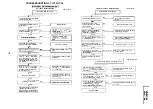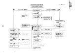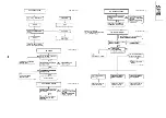
TROUBLESHOOTING
OF VCR SECTION
[
ELECTRICAL
I
VCR POWER TROUBLESHOOTING
FLOW CHART NO. l-l
The VCR is dead. (No power)
I
Unplug the AC power cord.
it a few minutes later.
I
I
I
Is the fuse
in the TV
power
Replace the fuse.
1
I
YES
I
Are the AT
and
lines
normal in the VCR
?
YES
Check fuse resistor and transistor
trouble of the
the
Is the AT
linenormal
YES
I
Are the AT
and
lines
properly connected with
Check poor soldering.
I
Replace
and I or
Does pin
of
change
from L to H level when
AT
line changes
to
with
the AC cord being plugged in or
ALL CLEAR button being pressed
and released ?
N O
Check pin
of
or
YES
Does pin
of
change
from L to H . level when
the power button is pressed to
turn the power on ?
N O
Check power key input to
and serial
clocks between
and
YES
Is the PC
line normal ?
YES
N
O
Check
P-CON
Signal at
pin
of
and
in the
TV mother
Is the PC
line normal
N O
I
YES
I
I
I
Check wire harness to mechanism
from mechanism (CAM Switches
and the sensor inputs to
reel sensor;)
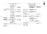
CASSETTE CONTROL TROUBLESHOOTING
FLOW CHART NO.
A
cassette tape Is not taken in.
Is the cassette housing
YES
Fix or replace the cassette
housing.
1
Does the start sensor cover
NO
become open when the cassette
Check the start sensor cover.
tape is inserted
I
I
1
Does the start sensor pin
of
go to
when the
cassette tape is inserted
N O
Check the start sensor and the way
up to pin
of
YES
Does
of
I
o to
level (about
when
e cassette tape is
Check pin
of
and all the
way up to pin
of
1
I
Does in
of
go to
V when the cassette tape
N O
Check
and
line.
is inserted
YES
Is the correct
e at the
N O
loading terminal w en the cassette
C h e c k b e t w e e n
a n d t h e
tape is
loading motor.
$-YES
Check and replace the loading
motor.
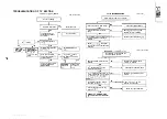
FLOW CHART NO.
A cassette tape taken in, but ejected at once.
r
1
Does start sensor pulse at pin
of
e from L to H
Check the start sensor and all the
level when t e cassette tape is loaded
way up to
Does end sensor pulse at pin
of
change from L
l
to H “level
N O
Check the end sensor and all the way
when the cassette tape is loaded
up to
J-YES
Do the cam switches A and 8 operate
loaded
when the cassette tape is
(at pins
and
(refer to MECHANISM flow chart)
N O
Check cam switches and all the way up
t o
I
I
Replace
Summary of Contents for VT-3428X
Page 78: ...m 3428X VT 51 28X IF Pack Unit RiWOOl7CEZZ 1 4 11 l e i t 1 I 2 I 3 I 4 I 5 I 6 1 78 ...
Page 82: ...VT 3428X VT 5128X I AWIO m I Au 10 f X I 7 I 8 I 9 I 10 I 11 I 12 I 82 ...
Page 90: ...VT 3428X VT 51 28X I t 7 I 8 I 9 I 10 I 11 I 12 I ...
Page 94: ...VT 3428X W 5128X 3 7 I 8 I 9 I 10 I 11 I 12 I 94 ...
Page 96: ...VT 3428X VT 51 28X TO Y C AUDIO CIRCUIT NCR 21 I I I I 7 I 8 I 9 I 10 I 11 I 12 I 96 ...
Page 100: ...m 3428X VT 51 28X Wiring Side f r 7 I 8 I 9 I 10 I 11 I 12 1 100 ...
Page 102: ...VT 3428X VT 51 28X I 7 I 8 I 9 I 10 I 11 102 1 12 I ...
Page 104: ...VT 3428X I m 5128X 1 7 I 8 I 9 I 10 I 11 I 12 I ...
Page 123: ...MECHANISM CHASSIS PARTS G F E I i 1 I 2 I 3 I 4 I 5 I 6 I 123 ...
Page 125: ...CASSETTE HOUSING CONTROL PARTS i T 3428X VT 51 28X 1 I 2 I 3 I 4 I 5 I 6 I 125 ...
Page 127: ...VT 3428X W 51 28X MODIEL VT 3428X CABINET AND MECHANICAL PARTS 1 I 2 I 3 I 4 I 5 I 6 127 ...
Page 128: ...W 3428X VT 51 28X I IO 9 0 3 7 128 ...
Page 130: ...VT 3428X VT 5128X I 0 I 0 ...
Page 132: ...MODELS VT 3428X AND VT 51 28X CABINET AND MECHANICAL PARTS I i 1 I 2 I 3 I 4 I 5 I 6 I 132 ...
Page 136: ...S H A R P TQ0023 S Printed in Japan 0 w s MW KD ...


