background image

Summary of Contents for Z-50

Page 1: ...nd 3 Unpacking and insta I o b 4 Supplies L w 1 51 comPonent location 61 COPYprocess 7 Paperfeed and transport section 81 Optical system 9 Fuser section i 10 Others 11 12 35 Electrical section Circuit diagramandtime chart 37 4 13 Actual wiring chart 50 SHARP CORPORATION J ...

Page 2: ...ng table Paper feed system Cassette and manual feeds Developing system Magnetic brush development 2 component developer Fusing system Heat roller type Light source Halogen lamp 1OOV series 200W 200V series 215W Power requirements Local supPly voltage 10 Power consumption 1 15 kW maximum 50 wh standby power down mode Physical dimensions 411 W x 41O D x 209 H mm 16 44 W x 16 4 D x 8 36 H inch Weight...

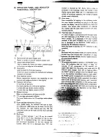
Page 3: ...mber is returned to 0 Every time a copy is produced in the multicopy mode the number in the display coun down When the is depressed in the middle of multicopy operation the number of copies already made is displayed Auto repeat j Upon completion of copying in the multicopy mode the copy number previously set returns to the copy numberset display Use of the CLEAR key resets the number One minute af...

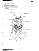
Page 4: ...he tape around the top of the package and open the flaps Remove the accesso container top padding and take out accessories Remove the upper packing cushion and take out the reachinc Dustcover instructionmanual andotherprintedmaterials Itainer Cassette upper paCkin9 CUShiOn Lowerpackingcushion 3 ...

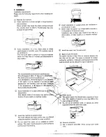
Page 5: ...red for proper cooling fan ventilation Adequate working space around the machine should also be allowed for ease of operation 4 The recommended environmental conditions are i 20 to 25 degrees C 68 to 77 degrees F 65 5 RH The nominal environment conditions are 10 to 30 degrees C 40 to 86 degrees F O t 85 RH S If the copier is to be installed in an area of higher temperature the humidity must be low...

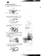
Page 6: ...from a new drum cartridge d Push in the drum cartridge all the way then close the upper frame Protectivecover ODOD D Never expose the drum to direct sunlight or touch the drum surface with your fingers Open the box containing the TD cartridge Remove the TD cartridge from the bag and shake horizontally four or five times c U j it Remove the cover from the TD cartridge Save the TD cartridge cover It...

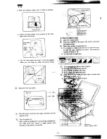
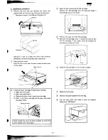
Page 7: ...tridge replacement the ready lamp may require a longer period No minutes or less before it turns ON t ihe c plug that P comas with the F2 T Prduct matches ymr wall outlet 4 How to mke a copy Opentheoriginal qver Place tie orig i the upper right corner and close the original cwer Select thenurnhr of copies desired If a mi ake is made press the key to clear the entry or hold the copy quantity key do...

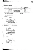
Page 8: ...4 DE U St 4or x 3 W0 pias for black 2 700 mpies for color for These are estimates only life will vary depending on A4 or letter size with 5 toned area actual usaaga NOTE How to identify the lot number TD rtridge xl 2 4 Developer kind Serial number Last digit of production year 6 1986 Production month 1 2 3 0 X Y Black developer JAPAN 5 Blue developer Black developer EXPORT 6 Brown developer Red de...

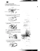
Page 9: ...perframe ralmw button Grasp the handle of the drum cartridge and pull the drum cartridge out NOTE Thedrum cartridge cannot beremovedorinwned unlessthe upper frame is open Remove the protective cover from the new drum cartridge Push in the drum cartridge all the way in then CIO the upper frame iy x c 2 r t _ T 1 A A Insert the TD cartridge then close the front cover Turn power on and make sure that...

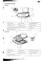
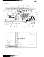
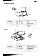
Page 10: ...paper entrv side POWER switch lever Manudfeedgutie Powersupplycord o Qmvinghandk wperentwtide colorcheckw dow Etittray Businesscard release lever 2 Open view 2 Drum cartridge Cleaning lever Upper frame release button o Fuser Transfer corona unit Fuser accessinglever Transfer corona cleaner 9 ...

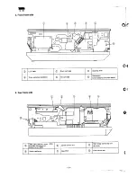
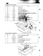
Page 11: ...lea i g lever To er alletiion co i er TD cartridge Doorswitch interlined for the main switch 4 Rear frame side 0 Table start position sensor M l e j rrun nsorati atorarm Highvoltaw transformerunit MTHVG Powertransformer Main PWB Powerswitchlever lo ...

Page 12: ...ntration sensor Paper entry sensor MS 1 Manualfeedpaparentry sensor o MS Paperfeedroller B Paperfead roller A ps plate Cassette paper feed solenoid PFS Transfer corona Q Separation roller Lower heat roller Heater lamp Upper heat roller Paper exit sensor MS 2 Thermistor thermal fuse thermal breaker Cooling fan main motor driven i 11 ...

Page 13: ...ensor Manual faad paper entry sansor Table mafi sition Table home ovarmn posmion sen LŠ Power switch 1 Senses i llation of e TD tigs in tie copier If the TD cartridge is not g h rn rga s m o e uss po r is not sug lied to the main w Name Main motor Toner motor Powar transformer Main and transfer high voltage units Discharge lamp Copy lamp Heater lamp Function Main drive motor alsodr n the cooling f...

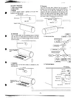
Page 14: ...charge lamp is projected over the drum to reduce electrical resistance of the OPC layer and remove any residual charge to evenly neutralize the drum surface Discharge lamp o t original The light neutralizes the negative charge The dark areas of the original do not reflect the light and an electro static latent image is formed on the drum surface 1 4 Copy lamp Selfoc lens m 3 T ve Remove any residu...

Page 15: ...rum sufiace is transferred onto the copy paper by applying a negative charge from the transfer corona to the back of the copy paper I r 1 Paper P J Transfer corona 5 paration The paper is separated from the drum by the remover tape and the separation roller I k T 6 Fusing Through a mmbination of heat and pressure the image is fused into the copy paper Lower heat roller 1 14 ...

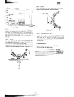
Page 16: ...s decreased the positive charge in the aluminium layer moves to neutral ize the negative charge present in the OPC layer c Discharge lamp F Step 2 Charge A uniform negative charge is applied over the OPC drum surface by the main corona unit Step 3 Exposure copY lamp SELFOC lens Light from the coPy lamp reflected from the original is projected onto the drum surface through the SELFOC lens The resis...

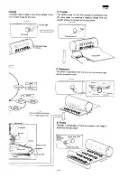
Page 17: ...the back of the copy paper As the transfer effect is 70 to 80 20 to 30 of the image remains on the drum residual toner even after the transfer Step 6 Cleaning Toner remaining on the drum is collected by the cleaner blade and stored in the toner collecting container Cleaner Residual toner Step 7 Discharge same as Step 1 Step 8 The transferred image is fixed permanently on the copy paper by the acti...

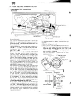
Page 18: ...the paper stopper plate The PS sensor block located on the original table lifts the paper stopper plate and al lows the coPy paper to continue through the paper guide to paper feed roller C The copy paper passesbetween the transfer corona and the drum and the image is transferred to the copy paper The remover tape strips the COPY paper from the drum and the separation roller transports it to the f...

Page 19: ...ted to paper feed roller B and the paper entry sensor MS1 There the paper is held temporarily by means of the PS plate in order to synchronize with the lead edW of the image on the drum Since paper feed roller B is continues to rotate the paper will be evenly pressed against the PS plate to correct for any paper feed skew Tension roller PS plate m Paper Paper feed roller A Spring clutch rfed As th...

Page 20: ...l to actuate within 3 seconds after the actuation of the MS3 Q In the course of copying a b c If the paper lead edge does not actuate MS2 within 2 3 seconds from the first actuation of MS5 after the table started to advance If MS2 is still actuated in 1 4 seconds after the discharge lamp turned off at the last copy in the single copy or multicopy mode If MS1 is not actuated at the timing that the ...

Page 21: ...the upper frame then remove the TD cartridge and the drum cartridge Remove the separation unit from the drum cartridge CAUTION Do not expose the drum cartridge to direct sunlight Separation unit Remove theremovertape from the separation unit E Removal of the MS2 Remove the ACCURIDE fixing screwS 2 crews and remove the table unit Original cover J 1 Rear frame side ACURI DE rail ti y A 1 i Remove th...

Page 22: ...connected to MS3 will be disconnected protrusion comes into contact with the paper feed latch Make sure that the lower side of paper feed roller A is parallel to the lower side of the paper feed frame The tolerance is O 5 Gear A n Paperfead roller A 6 ie b View of the paperfeed unit from the rearframeside Adjustment procedure Check the angle of paper feed roller A Change the hook position of the c...

Page 23: ...and 3 Unpacking and insta I o b 4 Supplies L w 1 51 ComPonent location 61 COPYprocess 7 Paperfeed and transport section 81 Optical system 9 Fuser section i 10 Others 11 12 35 Electrical section Circuit diagramandtime chart 37 4 13 Actual wiring chart 50 SHARP CORPORATION J ...

Page 24: ...ng table Paper feed system Cassette and manual feeds Developing system Magnetic brush development 2 component developer Fusing system Heat roller type Light source Halogen lamp 1OOV series 200W 200V series 215W Power requirements Local supPly voltage 10 Power consumption 1 15 kW maximum 50 wh standby power down mode Physical dimensions 411 W x 41O D x 209 H mm 16 44 W x 16 4 D x 8 36 H inch Weight...

Page 25: ...number is returned to 0 Every time a copy is produced in the multicopy mode the number in the display coun down When the is depressed in the middle of multicopy operation the number of copies already madeisdisplayed Auto repeat j Upon completion of copying in the multicopy mode the copy number previously set returns to the copy number set display Use of the CLEAR key resets the number One minute a...

Page 26: ...ape around the top of the package and open the flaps Remove the accesso container top padding and take out accessories Remove the upper packing cushion and take out the reachinc Dust cover instruction manual and other printed materials Itainer Cassette upper Packin9 CUShiOn Lower packing cushion 3 ...

Page 27: ...red for proper cooling fan ventilation Adequate working space around the machine should also be allowed for ease of operation 4 The recommended environmental conditions are i 20 to 25 degrees C 68 to 77 degrees F 65 5 RH The nominal environment conditions are 10 to 30 degrees C 40 to 86 degrees F O t 85 RH S If the copier is to be installed in an area of higher temperature the humidity must be low...

Page 28: ...from a new drum cartridge d Push in the drum cartridge all the way then close the upper frame Protective cover ODOD D Never expose the drum to direct sunlight or touch the drum surface with your fingers Open the box containing the TD cartridge Remove the TD cartridge from the bag and shake horizontally four or five times c U j it Remove the cover from the TD cartridge Save the TD cartridge cover I...

Page 29: ...artridge replacement the ready lamp may require a longer period No minutes or less before it turns ON t ihe C plu9 that P comas with the F2 T pr uct matches ymr wall outlet 4 How to mke a copy Opentheoriginal qver Place tie orig i the upper right corner and close the originalcwer Select thenurnbrof copies desired If a mi ake is made press the key to clear the entry or hold the copy quantity key do...

Page 30: ...4 DE U St 4or x 3 m0 pias for black 2 700 mpies for color for These are estimates only life will vary depending on A4 or letter size with 5 toned area actual usaaga NOTE How to identify the lot number TD rtridge xl 2 4 Developer kind Serial number Last digit of production year 6 1986 Production month 1 2 3 0 X Y Black developer JAPAN 5 Blue developer Black developer EXPORT 6 Brown developer Red de...

Page 31: ...perframe ralmw button Grasp the handle of the drum cartridge and pull the drum cartridge out NOTE Thedrum cartridge cannot beremovedorinwned unlessthe upper frame is open Remove the protective cover from the new drum cartridge Push in the drum cartridge all the way in then clo the upperframe iy x c 2 r t _ T 1 A A Insert the TD cartridge then close the front cover Turn power on and make sure that ...

Page 32: ...aper entrv side POWER switch lever Manudfeedgutie Powersupplycord o Qrrving handh WPerentwtide Colorcheckwhdow Etittray Businesscard release lever 2 Open view 2 Drum cartridge Cleaning lever Upper frame release button o Fuser Transfer corona unit Fuser accessinglever Transfer corona cleaner 9 ...

Page 33: ...lea i g lever To er alletiion co i er TD cartridge Doorswitch interlined for the main switch 4 Rear frame side 0 Table start position sensor M l e j rrun nsorati atorarm Highvoltaw transformerunit MTHVG Powertransformer Main PWB Powerswitchlever lo ...

Page 34: ... concentration sensor Paper entry sensor MS 1 Manualfeedpaparentry sensor o MS Paperfeedroller B Paperfead roller A ps plate Cassette paper feed solenoid PFS Transfercorona Q Separationroller Lowerheatroller Heaterlamp Upper heatroller Paperexit sensor MS 2 Thermistor thermalfuse thermal breaker Coolingfan mainmotordriven i 11 ...

Page 35: ...xit sensor Manual faad paper entry sansor Table mafi sition Table home ovarwn posmion sen Power switch 1 Senses i llation of e TD tigs in tie copier If the TD cartridge is not g h rn rga s m o e uss po r is not sug lied to the main w Name Main motor Toner motor Powar transformer Main and transfer high voltage units Discharge lamp Copy lamp Heater lamp Function Main drive motor alsodr m the cooling...

Page 36: ...charge lamp is projected over the drum to reduce electrical resistance of the OPC layer and remove any residual charge to evenly neutralize the drum surface Discharge lamp o t original The light neutralizes the negative charge The dark areas of the original do not reflect the light and an electro static latent image is formed on the drum surface 1 4 Copy lamp Selfoc lens m 3 T ve Remove any residu...

Page 37: ...rum sufiace is transferred onto the copy paper by applying a negative charge from the transfer corona to the back of the copy paper I r 1 Paper P J Transfer corona 5 paration The paper is separated from the drum by the remover tape and the separation roller I k T 6 Fusing Through a mmbination of heat and pressure the image is fused into the copy paper Lower heat roller 1 14 ...

Page 38: ...s decreased the positive charge in the aluminium layer moves to neutral ize the negative charge present in the OPC layer c Discharge lamp F Step 2 Charge A uniform negative charge is applied over the OPC drum surface by the main corona unit Step 3 Exposure copY lamp SELFOC lens Light from the coPy lamp reflected from the original is projected onto the drum surface through the SELFOC lens The resis...

Page 39: ...the back of the copy paper As the transfer effect is 70 to 80 20 to 30 of the image remains on the drum residual toner even after the transfer Step 6 Cleaning Toner remaining on the drum is collected by the cleaner blade and stored in the toner collecting container Cleaner Residual toner Step 7 Discharge same as Step 1 Step 8 The transferred image is fixed permanently on the copy paper by the acti...

Page 40: ...the paper stopper plate The PS sensor block located on the original table lifts the paper stopper plate and al lows the coPy paper to continue through the paper guide to paper feed roller C The copy paper passesbetween the transfer corona and the drum and the image is transferred to the copy paper The remover tape strips the COPY paper from the drum and the separation roller transports it to the f...

Page 41: ...ted to paper feed roller B and the paper entry sensor MS1 There the paper is held temporarily by means of the PS plate in order to synchronize with the lead edW of the image on the drum Since paper feed roller B is continues to rotate the paper will be evenly pressed against the PS plate to correct for any paper feed skew Tension roller PS plate m Paper Paper feed roller A Spring clutch rfed As th...

Page 42: ...il to actuate within 3 seconds after the actuation of the MS3 Q In the course of copying a b c If the paper lead edge does not actuate MS2 within 2 3 seconds from the first actuation of MS5 after the table started to advance If MS2 is still actuated in 1 4 seconds after the discharge lamp turned off at the last copy in the single copy or multicopy mode If MS1 is not actuated at the timing that the...

Page 43: ...the upper frame then remove the TD cartridge and the drum cartridge Remove the separation unit from the drum cartridge CAUTION Do not expose the drum cartridge to direct sunlight Separation unit Remove theremovertape from the5eparation unit E Removalof the MS2 Removethe ACCURIDE fixing screwS 2 crews and remove the table unit Original cover J 1 Rear frame side ACURI DE rail t i y A 1 i Remove the ...

Page 44: ... connected to MS3 will be disconnected protrusion comes into contact with the paper feed latch Make sure that the lower side of paper feed roller A is parallel to the lower side of the paper feed frame The tolerance is O 5 Gear A n Paperfead roller A 6 ie b View of the paperfeed unit from the rearframeside Adjustment procedure Check the angle of paper feed roller A Change the hook position of the ...

Page 45: ... on the drum A SELFOC lens is used so that the copy lamp light ima9e reaches the drum surface in a short distance Moving table method is used for exposure Exposure is controlled by varying the copy lamp voltage A photosensor diode is used in the optical system for sensing contrast in the original As the photosensor receives light reflected from the original the contrast of the original is determin...

Page 46: ...y the table drive gear train and the direction select solenoids TFS TRS A Table action S1OP star m Overwn I Paper ex t side Table IPauer entryside z w The table stops in the middle The table moves to the starting position paper exit side The table moves towards the paper entry side while exposing the original Begins to return from the overrun position and stops at the stop position In the multicop...

Page 47: ...is at rest TFS TRS OFF The solenoids TFS TRS are not energized The latch does not catch the clutch brake and both feed and return clutches are not active Therefore rotation of 6 gear A is not conveyed to gear F When the table is moving forward TFS ON TRS OFF The TFS is energized the latch catches the forward clutch brake Thus the forward clutch comes into action so that rotation of gear A is conve...

Page 48: ...it side side L J MS 5 actuator arm MS 4 actuator arm Immediately after the copy lamp is turned ON 0 1 second the TFS Table Feed Solenoid is energized Then the table starts moving forward and exposure is started for the original Although MS5 actuates while the table is being advanced it continues to advance At the second actuation of MS5 the table stops on the table over run position End of paper f...

Page 49: ...ext remove the copy lamp through the clearance between the exposure control plate and the reflector NOTE Change in the exposure control plate location may vary the exposure balance Side refletior R e side E 4 F Installation precautions a COPY larnP Install the copy lamp so that the protrusion on the lamp points away from the reflector b Exposure controi plate copy lampprotrusion Refletior Thermal ...

Page 50: ...lacement of the copy lamp regulator PWB or any of its components After replacement of theAEserssor Adjustment procedure Remove the optical unit and clean the surface of the sensor with a cloth dampened with alcohol NOTE Cleaning with dry cloth may leave dust on the sensor Replace the optical unit Clean the original cover Set the contrast select switch to the middle position Make a copy without an ...

Page 51: ... spring Fuser paper guide B 1A J p T Upper heat roller Thermal breaker Reset button Fuser compartment Thermistor the mal fuse unit accessinglever A Heat roller A teflon roller is used for the upper heat roller and a silicone rubber roller is used for the lower heat roller for 6 better toner fusing performance and paper separation Simple raising of the fuser compartment accessing lever separates th...

Page 52: ... reset using the reset button on the thermal breaker It does not reset automatically 2 Major component removal Upperheatroller Open the upper frame Remove the E ring and disconnect the two connectors Remove the boss on the front frame then the one on the rear frame side arrow marks a thru d Electrode cover R Fuser cover Electrode aver WI ele rode Rear frame ing b Fuser compartment a Lower heat rol...

Page 53: ...emove the upper fusar unit Remove the fuser cover Remove the tension spring Rotate the pawl in direction A and match the machined surface of the separator pawl shaft to the guide then remove it from the notch Saparator pawl shaft machined surface Tension spring I Separator pawl shaft Separator pawl shaft machined surface Guide Cut in the frame E Thermal breaker thermistor thermalfuse unit Remove t...

Page 54: ...hermistor Make sure that the center of the thermistor is in contact with the heat roller Z M 10 OTHERS 1 Drum counter Copy number can be checked on the mechanical counter under the drum drive gear Drum drive gear The counter in the figure indicates the copy number of 3210 bttom to top Counter cover 2 Main switch mechanismand premutions The main power supply can be turned on and off with the POWER ...

Page 55: ...CAUTION connect the connectors Then remove the black cover t Black Cover Corm tors Remove the 5 fixing screws on the power supply unit and disconnect the 2 connectors shown in the figure 4 Then lift the power supply unit out of the main body Power Supply PWB v MSW Do not remove transformer screws Red 2 when removing 6 Care must be taken not to close the front door with the doorswitch hole closed w...

Page 56: ...areas of the drum and develops the latent image on the drum The Magnetic roller is a rotating aluminum sleeve At the center of the MG Roller are stationary magnets These magnets hold and direct the developer The developer is composed of very fine magnetic filings and is used to transport the Toner from the developer to the drum As the MG Roller rotates it carries Developer and Toner The Magnetic F...

Page 57: ...m 1 L Ii A I I AA I I I P MM TM Relay circuit A Single chip microcomputer Switch sensor Driver circuit z Main PWB 1 a 9 Q t 2 Main PWB block diagram r 1 I I I I I I I I I I I I I I I I I I I I L 1 I I I A u DC power supply I I I I I I II IN I IC5 I J 4 1 I ...

Page 58: ...elect Display digit select Table feed solenoid control solenoid active with a high signal H 5 V Table return solenoid control solenoid active with a high signal H 5V Main corona control active with a high signal H 5V Transfer corona control active with a high signal H 5 V Copy lamp control lamp active with a high signal H 5 V Heater lamp control lamp active with a high signal H 5 V Reset active wi...

Page 59: ...es high voltage to the main and transfer coronas ON and OFF timing is controlled by a signai from the main PWB Powersupply PWB a Supplies voltages for the motors lamps solenoids transformers and PWB s Q MainPWB H hvdtWePWB Powersupply PWB CLRPWB OperationPWB A Operation PWB B m RdaVPWB Copy lamp regulator PWB a b Turns the copy lamp ON and OFF via signals from themain PWB Automatically controls th...

Page 60: ... z m F 1 a I m I v I m I N I I 3 ...

Page 61: ... I I 1 I I I 1 1 I I I 39 ...

Page 62: ...z a I L m I I NOISE I 6K I m ...

Page 63: ... z m r 2 2 z i w I Iill m i i 4 L 13 2 11 0 9 _ a 41 ...

Page 64: ...z a 1 42 ...

Page 65: ... r b e w I m I T I m I N I I I I J L _____ _ 4 II H ZD I 0 u ...

Page 66: ...z a m m I I 44 A f 5 5 ...

Page 67: ...z m a z u 1 I I Q e ...

Page 68: ...L L L r L r L I 1 I I I I I I I I I I I I I I I I I I I I I I I I I I I I I I I I I I I I I I I I I I I I I I _ L I I I L J I I I I I I I I I I I I I I I I I I I I I I I I I I I I I I 1 I I I I I 1 xl I I I I 1 i e ex ...

Page 69: ... 4 L 1 47 ...

Page 70: ...z s L 1 I c ...

Page 71: ... W m 6V I L I L i 5 7 TY w z ...

Page 72: ...I J Uum 11 0 sem I I 1 I L _ _ _ ...

Page 73: ...2 50 SHARP SHARP CORPORATION Information SystemsGroup Quality Reliability Control Center Yamatokoriyama Nara 639 11 Japan 1986 August Printed In Japan ...

Reviews: