background image


www.steambrite.com


|


4


Technical Service Manual 


Model:

  DriStorm134, 134H, 184,184H 


Revision 1:

    Dated 29 / 06 / 2011 


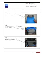
Q2: How to dismantle the front casing for servicing? 
 
A2: 

Step 1: 

Using the “Allen Driver” to undo the two “

HEX 

SOCKET CAP SCREWS” on the top.


Step 2: 

Using the “Hex screwdriver” to open the bottom 

screws at the bottom.


Step 3: 

Using the “Hex screwdriver” to open the back 

bottom side of the front casing. 


Summary of Contents for DriStorm134

Page 1: ...Revision 1 Dated 29 06 2011 Mobile Dehumidifiers 115V Models DriStorm134H DriStorm184H With Humidistat Timer Control DriStorm134 DriStorm184 With Timer Control TECHNICAL SERVICE MANUAL...

Page 2: ...o solve the dehumidifiers leaking problems 7 Q6 A6 The difference between the DriStorm 1XX models and DriStorm 1XXH models 8 9 Q7 A7 Where are the transformer terminal block compressor capacitor fan c...

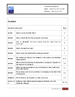
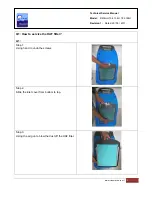
Page 3: ...l Model DriStorm134 134H 184 184H Revision 1 Dated 29 06 2011 Q1 How to service the HAF filter A1 Step 1 Using hand to undo the screws Step 2 Slide the inlet cover from bottom to top Step 3 Using the...

Page 4: ...06 2011 Q2 How to dismantle the front casing for servicing A2 Step 1 Using the Allen Driver to undo the two HEX SOCKET CAP SCREWS on the top Step 2 Using the Hex screwdriver to open the bottom screws...

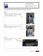
Page 5: ...casing from the main body for servicing A3 Step 1 Release the wire attached at the top of the casing Using the Allen Driver to undo the two HEX SOCKET CAP SCREWS on the left Step 2 Using the Allen Dri...

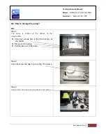
Page 6: ...How to change the pump A4 Step 1 The pump is located at the bottom of the dehumidifier z Undo four screws two in the front and two at the bottom z Disconnect the piping z Pull the tube out of the pump...

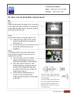
Page 7: ...in the pump is malfunction which led to the water in the reservoir can t be pumped out as it needs a Open the pump top cover and check whether the floating switch has been tightened and installed in...

Page 8: ...orm 1XX models and DriStorm 1XXH models A6 1 Electronic Board DriStorm 134H 184H z There is a hole on the electronic board z There is an extra socket for humidistat sensor z Some sockets are located i...

Page 9: ...e difference between the DriStorm 1XX models and DriStorm 1XXH models A6 Continue 2 Sensors DriStorm 134H 184H z The Humidistat sensor ambient temperature sensor are located in the front of the coil D...

Page 10: ...e control panel z The compressor capacitor round shape fan capacitor square shape are also located at the back of the curve shape metal plate just underneath the control panel DriStorm 184 184H z The...

Page 11: ...anel out of the plastic casing z See Annex 1 for DriStorm 134H 184H schematic diagram showing you how to connect the wires z The image on the right showing you what does the control panel look like Dr...

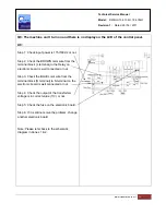
Page 12: ...e terminal block L terminal to the Relay on electronic board is well connected or not Step 3 Check the BLUE color wire from the terminal block N terminal to N terminal on the electronic board is well...

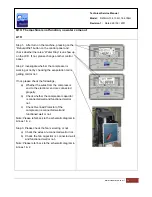
Page 13: ...g the evaporation coil is getting cold or not If not please check the followings a Whether the wires from the compressor end to the electronic end are connected properly b Check whether the compressor...

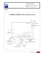
Page 14: ...www steambrite com 14 Technical Service Manual Model DriStorm134 134H 184 184H Revision 1 Dated 29 06 2011 Annex 1 SCHEMATIC DIAGRAM Model DriStorm 134H 184H...

Page 15: ...www steambrite com 15 Technical Service Manual Model DriStorm134 134H 184 184H Revision 1 Dated 29 06 2011 Annex 2 SCHEMATIC DIAGRAM Model DriStorm 134 184...

Reviews: