background image

__________________________________________________________________________ 

Bactrox Operations Manual                                                                                      28 

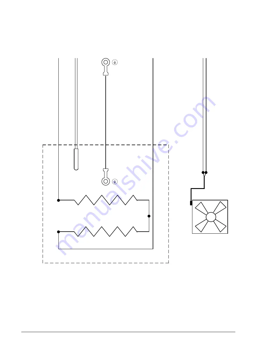
INCUBATOR & FAN BACTROX-2 

(9851366)


W

H

IT

E

 H

IG

H

 T

E

M

P

 1

4

G

R

E

D

 H

IG

H

 T

E

M

P

 1

4

G

G

R

E

E

N

/Y

E

L

L

O

W

 1

4

G

T

O

 O

T

P

 C

O

N

T

R

O

L

T

O

 T

B

2

#

8

INCUBATOR

T

O

 T

B

4

#

2

3

T

O

 T

B

1

#

3

B

L

A

C

K

 1

4

G

W

H

IT

E

 1

4

G

T

O

 O

T

P

 C

O

N

T

R

O

L

S

E

N

S

O

R

CHAMBER FAN 4880551

FAN PIGTAIL CORD

1800536

120V 65W 2350502

120V 65W 2350502


Summary of Contents for BACTROX

Page 1: ...CHAMBERS OPERATION MANUAL MODEL Bactrox Sheldon Manufacturing Inc P O Box 627 Cornelius Oregon 97113 EMAIL tech Shellab com INTERNET http www Shellab com 1 800 322 4897 503 640 3000 FAX 503 640 1366 Rev 9 11 12 4861671 ...

Page 2: ...ECTRIC CONDENSATE CONTROLER 9 7 INCUBATOR TEMPERATURE CONTROLLER SET OVER TEMPERATURE 9 8 CO2 CONTROL CALIBRATION 10 9 OXYGEN CONTROL CALIBRATION 11 10 POWER ON THE BACTROX 13 11 MAKING THE CHAMBER HYPOXIC 14 12 PASS BOX OPERATION 14 13 ENTERING THE CHAMBER 15 14 EXITING THE CHAMBER 15 15 MAINTENANCE 15 16 ACCESSORIES 16 17 TROUBLESHOOTING 17 18 BACTROX OPERATION TIPS 19 19 UNIT SPECIFICATIONS 20 ...

Page 3: ...rstanding of this unit including its proper function and operational characteristics Be sure operators are given adequate training before attempting to put the unit in service NOTE This equipment must be used only for its intended application any alterations or modifications will void your warranty 1 ORIENTATION Document Chart holder Pass Box GAS Connections Incubator Arm Port Door Storage Arm Por...

Page 4: ...le Gloves and Cuffs may be ordered from the Parts List The assembly allows gloveless chamber operation Figure 2 Arm port Doors CAUTION The Bactrox chambers have an efficient method of sealing the chamber by utilizing the Arm port doors as shown in Figure 3 The tightening knob on the Arm port doors should be turned just until the knob begins to grab DO NOT OVER TIGHTEN Damage can occur if too much ...

Page 5: ...l into and out of the chamber PASS BOX can be operated either automatically or manually The PASS BOX shelf allows for materials to be conveniently rolled from the PASS BOX into the chamber Figure 6 Incubator Bottom Shelf Spacer Three 3 are provided with the Bactrox Refer to Section 8 for installation and precautions Inner Airlock Door Oxygen Sensor and Box Incubator ...

Page 6: ...ta plate Check the data plate for voltage cycle and ampere requirements Plug the power cord into a PROPERLY GROUNDED earthed Power source OF THE CORRECT SIZE AND STYLE INDICATED ON THE UNIT NAMEPLATE RATING A separate circuit is recommended for this unit to prevent loss of product due to overloading or circuit failures caused by other equipment The supply voltage must match the nameplate voltage w...

Page 7: ...use hard tools such as metal wire brushes or steel wool Use non abrasive cleaners and soft tools such as plastic brushes Typical Bactrox Cleaning Procedure Remove the condensate collection vessel pan every week wash with soap and water and then disinfect with 70 alcohol solution Replace in the chamber Remove all shelves shelf supports shelf standards and shields Wash and disinfect as described in ...

Page 8: ...ition associated with the O2 within the chamber The MUTE indicator will light whenever the audible alarm has been deactivated 4 7 N2 INJECTING This pilot lamp is on whenever the oxygen control has been activated and is actively injecting N2 gas via the solenoid valve 4 8 AIR INJECTING This pilot lamp is on whenever the oxygen control has been activated and is actively injecting air via the solenoi...

Page 9: ...rom Bactrox into a suitable outlet Refer to the Installation Section of this manual for additional information Turn the power switch ON to verify power to the system 5 8 When the power switch to the Hypoxic Chamber is activated you should see a light in the back lit power switch the O2 and CO2 digital display panels illuminate along with a readout of the incubator temperature If any of these appea...

Page 10: ...2 controller has alarm indicators for high and low alarm conditions that are activated whenever the actual CO2 is 1 above or below the set point Audible Alarms Both controls have audible alarms that are activated when either of the HIGH or LOW indicators is activated 7 8 Muting Audible Alarms The audible alarms can be muted for a single alarm occurrence by pressing and holding down EITHER the UP o...

Page 11: ...ead CO2 concentration in WARNING The fluid used inside this fyrite instrument is poisonous and corrosive If taken internally could result in serious injury or death The fyrite indicator will come with a complete set of detailed instructions which should be followed carefully In the event of a spill or accidental body contact with the fyrite fluid follow the instructions on the refill bottle carefu...

Page 12: ...aved into that file as reading is taken 9 5 9 Plug in the Oxygen Calibration Pump into an electrical outlet and press the power button to turn on the pump Hook up the hose to the calibration port on the left hand corner of the unit 9 5 10 Set the O2 setpoint to OFF by holding down the down arrow on the SET OXYGEN Control under the digital O2 display Let the control stabilize at atmosphere for at l...

Page 13: ... 7 To enter the offset calibration push and hold both up and down arrow simultaneously until CO flashes and then the current display value flashes then release the buttons 9 6 8 While the current display value is flashing use the up or down arrow to change the value in the display to match the calibration gas 9 6 9 After the value is entered the display will stop flashing after 5 seconds if no but...

Page 14: ...ould be snug DO NOT OVER TIGHTEN Damage can occur if too much force is placed on the Arm port door assembly When the knob just begins to grab the tightening bolt has reached its maximum point Over tightening will cause the bolt to slip inside the handle and cause leakage Purging the Chamber 11 5 Turn Power Switch to the I On position on the Control Module 11 6 Note the reading on the gas regulator...

Page 15: ...he arm ports 14 EXITING THE CHAMBER 14 1 Doors are used to seal the Arm ports while the chamber is not in use Doors can be stored using the holders provided while the chamber is in use Assembly consists of an Arm port door tightening knob and locking bar Doors are secured by turning the locking bars horizontally to pass through the cutouts in chamber then turning locking bars vertical and tighteni...

Page 16: ... time Provides work bench to support Bactrox chambers Chamber Stand height 30 Stands feature locking casters and storage space Model 2002 B Nitrogen Gas Regulator CO2 Gas Regulator Optional accessory used in a two gas chamber Part 7150500 Optional accessory used in a two gas chamber Part 7150500 Cleaner Plexiglas Cleaner Benzalkonium Chloride 1060503 8 oz size Plexiglas Scratch Remover 1060504 8 o...

Page 17: ... switch once then release D Start button inoperative D Replace start button E No power to controller check power light on Controller E1 Check for 24 volt DC out of power supply E2 Check for continuity between power supply and controller II INCUBATOR Problem Possible Cause Solution Steady digital readout matches set point but actual temperature does not A Temperature Controller out of calibration A...

Page 18: ...cted is around 50 cc each day of chamber use Excessive moisture buildup in chamber A Thermoelectric condensate controller fan is not operating A Replace fan B Ambient room temperature too low B1 Maintain room temperature a bit higher B2 Cover chamber with a blanket overnight as means of installation C Air conditioner unit directly above chamber C Relocate chamber redirect the air conditioning duct...

Page 19: ...s consumption can be reduced by balancing arm movements For example when extending the right arm into the chamber bring the left arm close to the front of the chamber thus balancing the pressure and reducing gas displaced by area Aborting PASS BOX PURGE CYCLE The automatic PASS BOX can be aborted by pressing and holding the START PASS BOX PURGE button for five 5 seconds If a user forgets to place ...

Page 20: ...nches Exterior Dimensions W x D x H Inches Chamber Capacity Shipping Weight Unit Weight BACTROX BACTROX 2 48 5 x 31 0 x 32 6 300 plates Model Number Temperature Range Control Temperature Uniformity O2 Range CO2 Range BACTROX BACTROX 2 Ambient 8 to 60C 0 1C 0 35C 37C 0 20 0 20 Electrical Model Volts Amps VA Cycles BACTROX 120 11 1100 50 60 hz BACTROX 2 240 6 1100 50 60 hz ...

Page 21: ...2 12 TB1 2 TB7 18 TB7 13 TB8 20 TB8 19 TB7 16 TB8 21 TB7 14 TB7 15 TB4 19 TB4 21 TB4 23 TB4 22 TB4 20 TB5 6 TB5 1 TB6 12 TB6 7 TB6 8 TB6 9 TB6 10 BLACK 14G BLACK 14G BLACK 14G BLACK 14G BLACK 14G BLACK 14G BLACK 14G BLACK 18G BLACK 18G WHITE 18G WHITE 18G WHITE 14G WHITE 14G WHITE 14G WHITE 14G WHITE 14G WHITE 14G WHITE 14G WHITE 14G WHITE 14G WHITE 14G WHITE 14G WHITE 14G WHITE 14G WHITE 14G WHIT...

Page 22: ... TB1 4 TB2 10 TB1 5 TB2 7 TB1 6 TB2 12 TB1 2 TB7 18 TB7 13 TB8 20 TB8 19 TB7 16 TB8 21 TB7 14 TB7 15 TB4 19 TB4 21 TB4 23 TB4 22 TB4 20 TB5 6 TB5 1 TB6 12 TB6 7 TB6 8 TB6 9 TB6 10 BLACK 14G BLACK 14G BLACK 14G BLACK 14G BLACK 14G BLACK 14G BLACK 14G BLACK 18G BLACK 18G WHITE 18G WHITE 18G WHITE 14G WHITE 14G WHITE 14G WHITE 14G WHITE 14G WHITE 14G WHITE 14G WHITE 14G WHITE 14G WHITE 14G WHITE 14G ...

Page 23: ...B6 7 TB6 8 TB6 9 TB6 10 TB7 13 TB7 14 TB7 15 TB7 16 TB8 21 TB8 19 TB8 20 TTB1 TTB2 TTB2 1 TTB2 2 TTB2 3 TTB2 4 24VDC POWER SUPPLY 6750516 N2 PURGE N2 CO2 12VDC POWER SUPPLY 6750514 PURGE TIMER 8250513 1 2 3 8000547 8000547 8000542 SOLENOIDS 8600528 80K OHMS J12 RED 18G BLACK 18G BLACK 18G RED 18G BLACK 18G RED 18G RED 18G TB5 2 TB5 3 TB5 4 TB5 5 TB5 6 TB6 11 TB6 12 TB7 17 TB7 18 TB8 22 TB8 23 TB8 ...

Page 24: ...TB6 7 TB6 8 TB6 9 TB6 10 TB7 13 TB7 14 TB7 15 TB7 16 TB8 21 TB8 19 TB8 20 TTB1 TTB2 TTB2 1 TTB2 2 TTB2 3 TTB2 4 24VDC POWER SUPPLY 6750516 N2 PURGE N2 CO2 12VDC POWER SUPPLY 6750514 PURGE TIMER 8250510 8000547 8000547 8000542 SOLENOIDS 8600529 80K OHMS J12 RED 18G BLACK 18G BLACK 18G RED 18G BLACK 18G RED 18G RED 18G TB5 2 TB5 3 TB5 4 TB5 5 TB5 6 TB6 11 TB6 12 TB7 17 TB7 18 TB8 21 TB8 21 TB8 21 BL...

Page 25: ...WHITE WHITE WHITE WHITE WHITE HT BLACK BLACK BLACK BLACK BLACK BLACK WHITE RED RED ORANGE RED HT GREY GREY BLACK BLUE YELLOW BROWN WHITE RED BLACK RED 18G BLACK 18G RED 18G BLACK 18G RED 18G BLACK 18G BLACK 18G RED 18G TTB1 4 TTB1 3 TTB1 15 TTB1 16 BROWN 24G WHITE 24G BROWN 24G WHITE 24G TTB1 13 TTB1 14 RED 24G BLACK 24G TEMPERATURE SENSOR 8100500 TO RS232 SOCKET J10 TO BUSS CONN J12 TEMP DISPLAY ...

Page 26: ... WHITE WHITE WHITE WHITE WHITE HT BLACK BLACK BLACK BLACK BLACK BLACK WHITE RED RED ORANGE RED HT GREY GREY BLACK BLUE YELLOW BROWN WHITE RED BLACK RED 18G BLACK 18G RED 18G BLACK 18G RED 18G BLACK 18G BLACK 18G RED 18G TTB1 4 TTB1 3 TTB1 15 TTB1 16 BROWN 24G WHITE 24G BROWN 24G WHITE 24G TTB1 13 TTB1 14 RED 24G BLACK 24G TEMPERATURE SENSOR 8100500 TO RS232 SOCKET J10 TO BUSS CONN J12 TEMP DISPLAY...

Page 27: ...ox Operations Manual 27 INCUBATOR FAN BACTROX 9851361 WHITE HIGH TEMP 14G RED HIGH TEMP 14G GREEN YELLOW 14G TO OTP CONTROL TO TB2 8 INCUBATOR TO TB4 23 TO TB1 3 BLACK 14G WHITE 14G TO OTP CONTROL SENSOR CHAMBER FAN 4880550 FAN PIGTAIL CORD 1800536 120V 65W 2350502 120V 65W 2350502 ...

Page 28: ...x Operations Manual 28 INCUBATOR FAN BACTROX 2 9851366 WHITE HIGH TEMP 14G RED HIGH TEMP 14G GREEN YELLOW 14G TO OTP CONTROL TO TB2 8 INCUBATOR TO TB4 23 TO TB1 3 BLACK 14G WHITE 14G TO OTP CONTROL SENSOR CHAMBER FAN 4880551 FAN PIGTAIL CORD 1800536 120V 65W 2350502 120V 65W 2350502 ...

Page 29: ...________________________________________ Bactrox Operations Manual 29 CHILLER OUTLET BACTROX 9851362 R R R B B B TO TTB1 1 TO TTB1 2 RED 18G BLACK 18G ALL END STRIP 375 AND SOLIDER TIN TB7 11 TB8 24 BLACK 14G WHITE 14G GREEN YELLOW 14G ...

Page 30: ..._______________________________________ Bactrox Operations Manual 30 CHILLER OUTLET BACTROX 2 9851367 R R R B B B TO TTB1 1 TO TTB1 2 RED 18G BLACK 18G ALL END STRIP 375 AND SOLIDER TIN TB7 11 TB8 24 BLACK 14G WHITE 14G GREEN YELLOW 14G ...

Page 31: ...S THROUGH BOX CO2 VALVE N2 VALVE PURGE VALVE N2 CO2 SAMPLE PORT O2 CALIBRATION PORT CO2 REG N2 REG GAS FILTERS 2800525 FITTING LIST 3100517 X 10 PCS 3100516 X 5 PCS 3100519 X 9 PCS 3100518 X 1 PCS PASS BOX VENT SOLENOID VALVES SET 10 PSI SET 10 PSI REGULATORS 7150510 3100698 X 1 PCS MAIN CHAMBER VENT IN OUT IN IN OUT OUT IN OUT O2 SENSOR BOX CONDENSTATE DRAIN TUBE ...

Page 32: ...UE 3450506 3450506 1 LIGHT LED 4650547 1 LIGHT OTP SAFETY 4650553 4650553 1 OTP SAFETY ALARM 0250501 0250502 1 OUTLET VACUUM PUMP 6100525 6100531 1 POWER CORD 1800516 1800541 1 POWER CORD BACLOOP LIGHTBOX 1800516 1800541 1 SOLENOID CHAMBER GAS 8600528 8600529 1 SOLENOID GAS 1 8600528 8600529 1 SOLENOID GAS 2 8600528 8600529 1 SWITCH AUTO START RESET 7850531 7850531 1 SWITCH BACLOOP LIGHTBOX 785057...

Reviews: