9
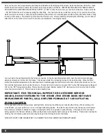
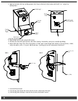
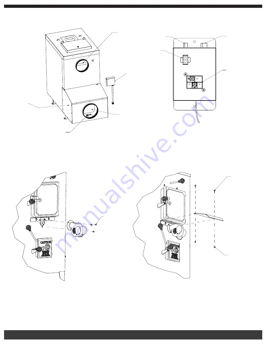
3. Align the fan limit control box with the gasket to the 4 holes on the back of the furnace with four #10 x ¾” screws for a
watertight seal.
4. Mount blower service cover using 23 #10 screws.
5. Pass the wire conduit through the hole on the blower housing. Reinstall the locking nut on weather tight fitting.
6. Mount draft motor to the front of the unit using three ¼” bolts, pass conduit through tube located on lower right corner. Attach
conduit clip with one #10 x ¾” screw to right inner panel. Insert plug into control center marked “draft motor.”
7. Insert draft blower shield.
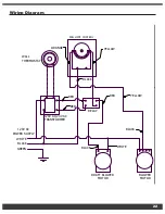
8. Insert the plug from the fan limit control into the control center marked “fan limit.”
9. Insert the plug from the blower motor into the control center marked “blower.”
1/4-20 Screw
STEP 6
STEP 7
HOT AIR SUPPLY
BLOWER
SERVICE
COVER
CONTROL CENTER
(SEE CLOSE-UP DIAGRAM)
FAN LIMIT CONTROL
COLD AIR RETURN
TRANSFORMER FOR
THERMOSTAT WIRE
BLOWER MOTOR
A
B
Blower
Service
Cover
Control Center
(See Close-Up Diagram )
Hot Air Supply
Fan Limit
Control
Cold Air
Return
Blower
Motor
Transformer for
Thermostat Wire
1/4-20 x 3/4 Bolt
1/4-20 Nut
1/4 - 20 Nut
1/4 - 20 x 3/4
Bolt


