background image

3

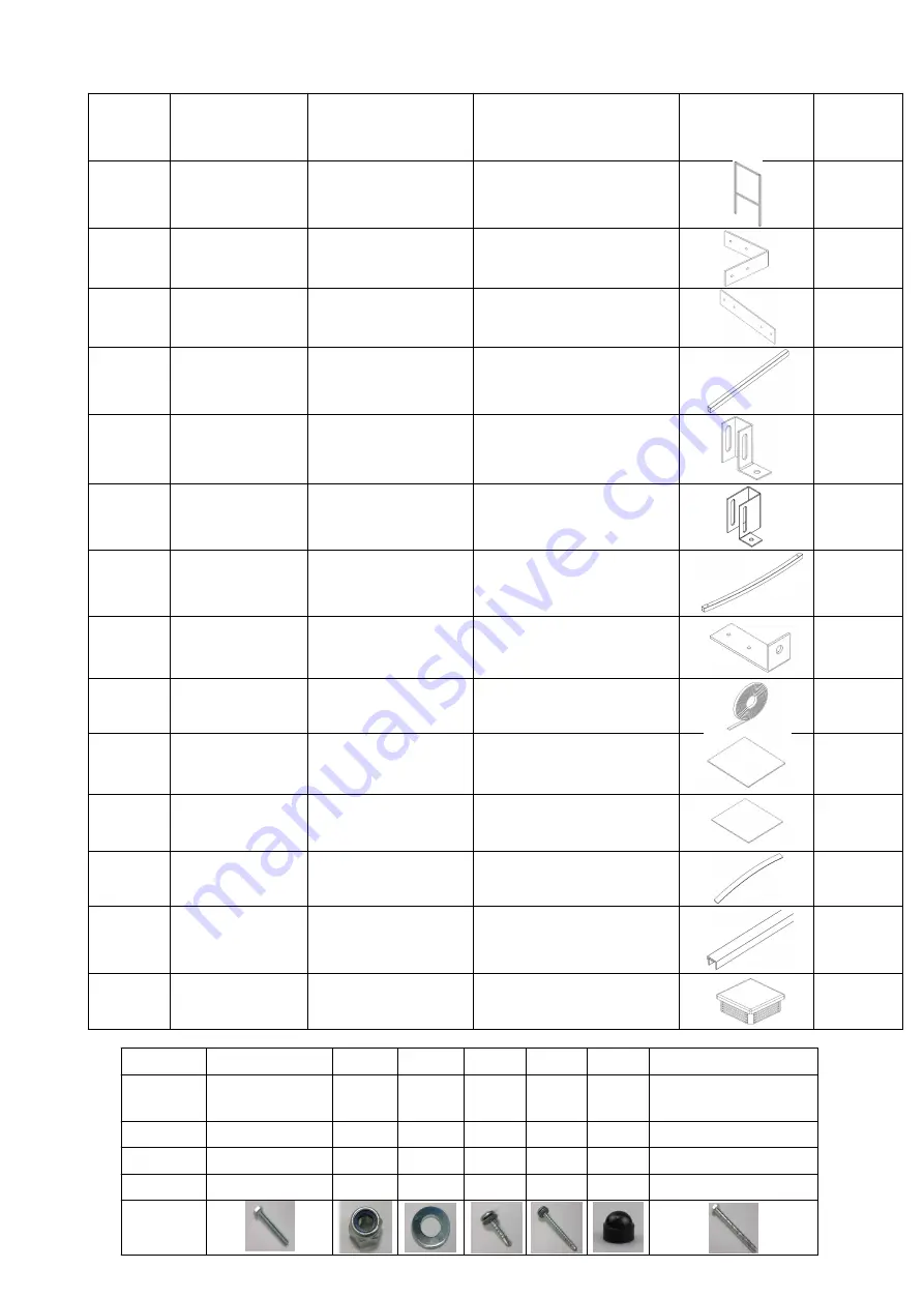
PARTS LIST

ITEM 

NO.

PART NO.

DESCRIPTION

DIMENSION

IMAGE

QTY.

1

S1 

FRAME

2000x1035

6

2

CB1 

BRACKET

110x110

6

3

JF1 

BRACKET

106x110x40

6

4

ST1 

ROOF TIE

1025x40x40

1

5

FT1

FOOT

109x100x40

4

6

FT3 

FOOT

109x100x40

4

7

R1

ROOF RAFTER

1130x40x40

4

8

RB1

BRACKET

110x46

12

9

SS

SEALING STRIP

TRIM TO 1130

2 ROLLS

10

PCE1

ROOF PANEL

1130x1050

2

11

PCC1

ROOF PANEL

1130x1030

1

12

RC1

ROOF STRIP

1130

4

13

2MD

ROOF EDGING

TRIM TO FIT

4

14

EC40

END CAP

40x40

10

Fittings Bolt set M10

T25

T50

BTANCM12100

M10 x 60 mm

Nut Washer

25 mm 

Tech 

screw

50 mm 

Tech 

screw

Black 

Caps

M10/12 x 100 mm 

Concrete Bolt

Pack A

30

30

60

72

30

60

8

Required

16

16

32

32

72

24

8

Spare

14

14

28

28

0

6

0

Image

Summary of Contents for SR1552

Page 1: ...Assembly Instructions Product Code SR1552 Doc No SR152 02 240317 UK...

Page 2: ...10 12 9 2 1 6 5 4 13 3 7 8 11 10 2 Tools required Drill Screwdriver Mallet Hack saw Spanner Torx bit Exploded View...

Page 3: ...4 8 RB1 BRACKET 110x46 12 9 SS SEALING STRIP TRIM TO 1130 2 ROLLS 10 PCE1 ROOF PANEL 1130x1050 2 11 PCC1 ROOF PANEL 1130x1030 1 12 RC1 ROOF STRIP 1130 4 13 2MD ROOF EDGING TRIM TO FIT 4 14 EC40 END C...

Page 4: ...mm Tec Screws are for the roof panels only Check overall dimensions to ensure correct alignment CB1 BRACKET CB1 BRACKET ENSURE CORRECT ALIGNMENT ON BOTH SIDES Step 1 Assemble main structure S1 Frames...

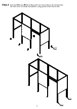
Page 5: ...ST1 S1 CB1 JF1 CB1 JF1 ST1 S1 Step 2 Attach ST1 Roof Tie and Final S1 to the structure using CB1 and JF1 Brackets 5...

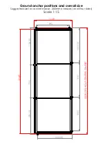
Page 6: ...FT3 FT1 FT3 FT1 Step 3 Bolt the FT1and FT3 Foot Brackets to the bottom of the frames and secure in desired position using ground anchor bolts 6...

Page 7: ...1035 1075 1035 R1 RB1 RB1 R1 Step 4 Screw RB1 Brackets to the top of the frame and bolt R1 Rafters to framework 7 FRONT VIEW...

Page 8: ...LE 1 1 5 SS Step 5 Attach two Sealing strips to the top of each rafter then place PCE1 and PCC2 Panels on top of the strips leaving a small gap between each Apply more sealing strips to the top of the...

Page 9: ...mm Tech screws then attach the 2MD Edge Trim to the outer edges of the panels Then fit the black plastic caps on exposed nuts and bolts Fit the square plastic end caps to any open ends of box sections...

Page 10: ...139 1044 50 3228 2193 HOLE CENTERS ON FEET 3149 1044 50 1035 1035 1136 50 995 1096 50 Ground anchor positions and overall size Suggested size for concrete base 200mm oversizes on all four sides Scale...

Page 11: ...NOTES 11...

Page 12: ...larly with soapy water Ensure all fitting are tight for example after a big storm Touch up any exposed metal should it get scratched CONTACT DETAILS Email Sales shelters4less co uk Web www shelters4le...

Reviews: