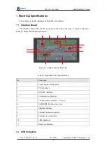
Dobot M1 User Guide
3
Hardware
Installation
Issue V1.0.4 (2018-01-31)
User Guide
Copyright © Yuejiang Technology Co., Ltd
27
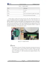
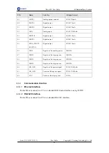
DOUT17) of the base I/O interface. The red one and the black one are connected to
the VCC_24V pin on the base I/O interface and the PGND pin on the CAN bus
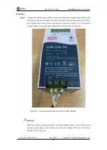
interface respectively, as shown in Figure 3.20, and you need to tighten them with a
straight screwdriver. The description in this topic is for reference only. Please choose
the appropriate interface to connect the relay. For details, please see
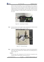
Figure 3.20 Connect relay to I/O interface
Figure 3.21 Push down the solder
NOTE
The rated voltage of the soldering station is 220V, which may be not supported in some
countries. Please use a transformer for conversion if you need.


