Dobot M1 User Guide
4
Electrical
Specifications
Issue V1.0.4 (2018-01-31)
User Guide
Copyright © Yuejiang Technology Co., Ltd
30
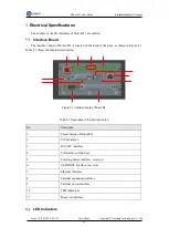
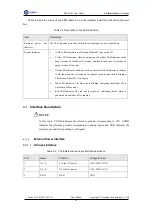
lists the status of the LED indicators on the interface board and the external power
box
Table 4.2 Description of the LED indicators
Item
Description
External
power
box
indicator
The LED indicator is steady on when the external power box is powered on.
System indicator
All the LED indicators are off when Dobot M1 is powered off
Yellow LED indicator: when powering on, the yellow LED indicator in the
base is steady on for about 15 seconds, and then blinks once. It is steady on
again for about 5 seconds
Green LED indicator: when powered on, the yellow LED indicator in the base
is off, the green one is steady on for about 5 seconds, and then is blinking.
That means, Dobot M1 is in service
Blue LED indicator: The blue one is blinking, indicating that Dobot M1 is
working in offline mode
Red LED indicator: The red one is steady on, indicating that an alarm is
generated when Dobot M1 is running
Interface Description
NOTICE
In this topic, PGND indicates the reference ground corresponding to 24V, AGND
indicates the reference ground corresponding to analog signal, and GND indicates the
reference ground corresponding to all signals.
External Power Interface
4.3.1.1
AC Input Interface
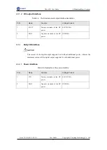
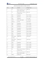
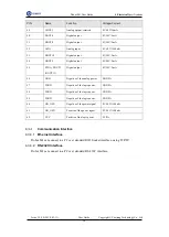
Table 4.3 The External power input interface description
PIN
Name
Function
Voltage/Current
1
AC_L
L of the AC power
110V-240V AC/3A
2
AC_N
N of the AC power
110V-240V AC/3A
3
GND
GND
GND


