Dobot M1 User Guide
4
Electrical
Specifications
Issue V1.0.4 (2018-01-31)
User Guide
Copyright © Yuejiang Technology Co., Ltd
36
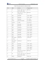
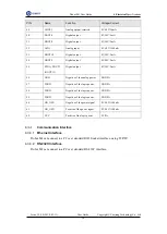
PIN
Name
Function
Voltage/Current
49
AOUT1
Analog output, reserved
0V-10V/10mA
50
DOUT6
Digital output
0V,24V/2mA
51
DOUT8
Digital output
0V,24V/2mA
52
AIN1
Analog input
0V-10V/<100mA
53
DOUT10
Digital output
0V,24V/2mA
54
DOUT9
Digital output
0V,24V/2mA
55
FPGA_DOUT1
(DOUT11)
Digital output
0V,24V/2mA
56
GND
Negative of the analog power
GND/1A
57
PGND
Negative of the logic power
GND/5A
58
PGND
Negative of the logic power
GND/5A
59
PGND
Negative of the logic power
GND/5A
60
ON_OFF-
Negative of the power signal
0V-24V/<100mA
61
Positive of the power signal
0V-24V/<100mA
62
VCC
Positive of the logic power
5V/2A
Communication Interface
4.3.4.1
Ethernet Interface
Dobot M1 can connect to a PC over standard RJ45 Socket interface, using TCP/IP.
4.3.4.2
RS-232C Interface
Dobot M1 can connect to a PC over standard RS-232C interface.


