10
Assembly Procedure
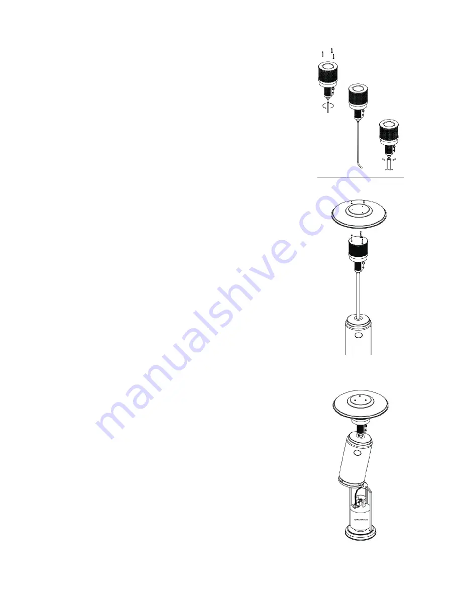
Step 4
4-1
Secure the 3 pcs 90 mm pins (reflector support bolts)
on the cap of flame screen.
4-2
Connect the gas hose to the tapered end of the gas
pipe and secure with metal clamp . (For gas hose with
threaded connectors, bind 2 or more rounds of plumbing
tape around the gas pipe for security .)
4-3
Bind 2 or more rounds of Teflon plumbing tape around
the gas burner inlet connector and connect the gas pipe .
Use a wrench to tighten the connection .
4-4
Fix the completed burner unit to the post by 4 pcs M6 x
10 mm bolts .
Step 5
5-1
Put Ø8 mm washer on each reflector support bolt.
5-2
Fasten the reflector with 3 pcs washers and 3 pcs M8
mm castle nuts .
Step 6
6-1
Lift the tank housing and rest it on the post plate .
6-2
Connect the other end of gas hose to the regulator
and secure with metal clamp . (For gas hose with threaded
connectors, bind 2 or more rounds of plumbing tape
around the regulator outlet connector before connecting
the gas hose for security .)
6-3
Connect the regulator to the gas cylinder and tighten it
with adjustable wrench .
6-4
Put gas cylinder on the stand .
Summary of Contents for 901233
Page 18: ...18 Customer Service ...
Page 19: ...19 Customer Service ...


