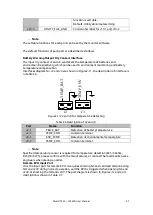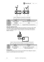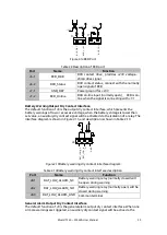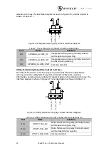
Shield T3 60 – 500KVA User Manual
47
5.0
6.0
2.5
0.0
0.0
0.0
0.5
0.6
0.2
57
55
0
513
0
0.6
0.4
0.2
57
55
0
513
0
0.0
0.0
0.0
0.0
22
0.0
0.0
0.0
0.0
25.0
25.0
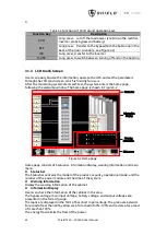
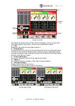
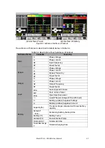
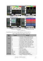
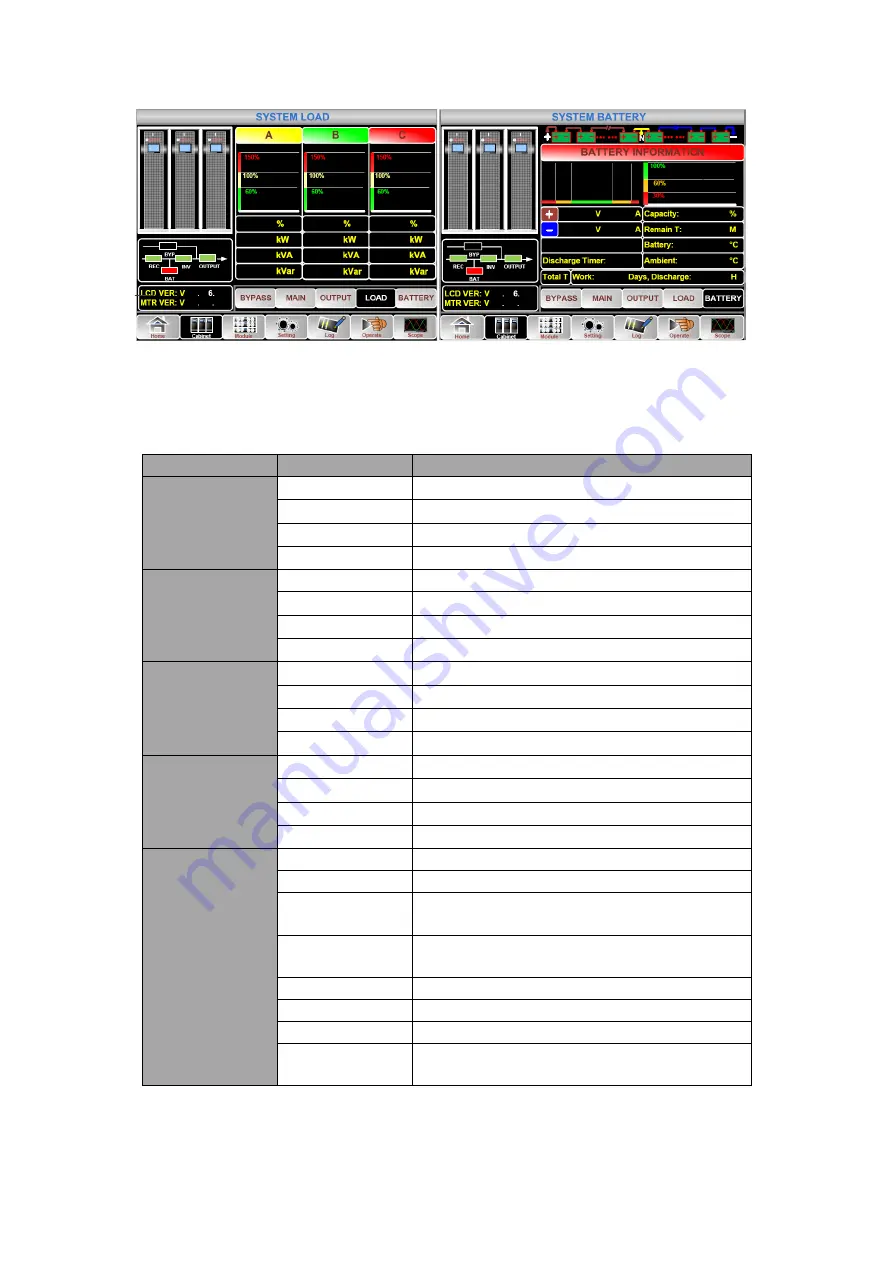
(d) Interface of Load (d) Interface of Battery
Figure3-5
Submenu interface of Cabinet
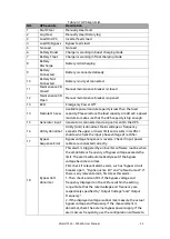
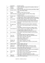
The submenu of Cabinet is described in details below in
Table 3-4
Description of each submenu of Cabinet
Submenu Name
Contents
Meaning
Main
V
Phase voltage
A
Phase current
Hz
Input frequency
PF
Power factor
Bypass
V
Phase voltage
A
Phase current
Hz
Bypass frequency
PF
Power factor
Output
V
Phase voltage
A
Phase current
Hz
Output frequency
PF
Power factor
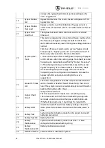
Load
kVA
Sout: Apparent Power
kW
Pout: Active Power
kVar
Qout: Reactive power
%
Load (The percentage of the UPS load)
Battery
V
Battery positive/negative Voltage
A
Battery positive/negative Current
Capacity (%)
The percentage compared with new battery
capacity
Remain T
(
Min
)
Remaining battery backup time
Battery(
℃
)
Battery Temp
Ambient(
℃
)
Environmental Temp
Total Work T
Total work time
Total Discharge
T
Total discharging time

