background image

109 


No 

Abbr. 

Function description 

Control 

  mode 

Setting 

range 

Unit 

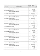
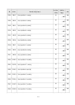
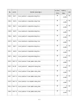
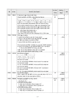
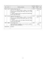
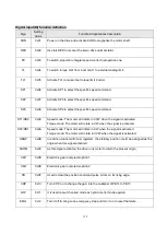
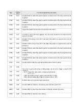
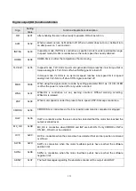
PE69  PDEF34  PATH#34 definition 

Please refer to PE03 instruction. 

Pr 

00000000h 

FFFFFFFFh


PE70  PDAT34  PATH#34 data 

Please refer to PE04 instruction. 

Pr 

-(2

31

+1) 

~(2

31

-1) 

PE71  PDEF35  PATH#35 definition 

Please refer to PE03 instruction. 

Pr 

00000000h 

FFFFFFFFh


PE72  PDAT35  PATH#35 data 

Please refer to PE04 instruction. 

Pr 

-(2

31

+1) 

~(2

31

-1) 

PE73  PDEF36  PATH#36 definition 

Please refer to PE03 instruction. 

Pr 

00000000h 

FFFFFFFFh


PE74  PDAT36  PATH#36 data 

Please refer to PE04 instruction. 

Pr 

-(2

31

+1) 

~(2

31

-1) 

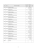
PE75  PDEF37  PATH#37 definition 

Please refer to PE03 instruction. 

Pr 

00000000h 

FFFFFFFFh


PE76  PDAT37  PATH#37 data 

Please refer to PE04 instruction. 

Pr 

-(2

31

+1) 

~(2

31

-1) 

PE77  PDEF38  PATH#38 definition 

Please refer to PE03 instruction. 

Pr 

00000000h 

FFFFFFFFh


PE78  PDAT38  PATH#38 data 

Please refer to PE04 instruction. 

Pr 

-(2

31

+1) 

~(2

31

-1) 

PE79  PDEF39  PATH#39 definition 

Please refer to PE03 instruction. 

Pr 

00000000h 

FFFFFFFFh


PE80  PDAT39  PATH#39 data 

Please refer to PE04 instruction. 

Pr 

-(2

31

+1) 

~(2

31

-1) 

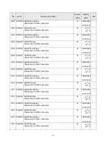
PE81  PDEF40  PATH#40 definition 

Please refer to PE03 instruction. 

Pr 

00000000h 

FFFFFFFFh


PE82  PDAT40  PATH#40 data 

Please refer to PE04 instruction. 

Pr 

-(2

31

+1) 

~(2

31

-1) 

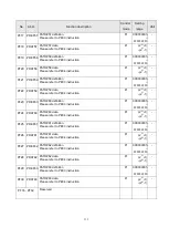
PE83  PDEF41  PATH#41 definition 

Please refer to PE03 instruction. 

Pr 

00000000h 

FFFFFFFFh


PE84  PDAT41  PATH#41 data 

Please refer to PE04 instruction. 

Pr 

-(2

31

+1) 

~(2

31

-1) 


Summary of Contents for SDE Series

Page 1: ... conditions resulting in death or injury It indicates that incorrect operation may cause hazards resulting in injury to person or damage to the product Note that the CAUTION level may lead to a serious consequence by cases Be sure to follow the instructions of both levels to keep personnel safety well What must not be done and what must be done are indicated by the following marks It indicates wha...

Page 2: ... servo drive or motor which has become faulty Otherwise a large current flow may cause a fire Do not connect a commercial power supply to the U V W terminals of drive Otherwise a fire may be caused and the servo drive will be damaged When an external regenerative brake resistor is used check the specification recommended Otherwise a regenerative brake transistor fault or the like may overheat the ...

Page 3: ...d environmental conditions Firmly attach the servo motor Otherwise it may come off during operation For safety of personnel always cover the rotating and moving parts Never impact the servo motor or shaft especially when coupling the servo motor to the machine The encoder may become faulty Do not subject the servo motor shaft to more than the permissible load Otherwise the shaft may be broken When...

Page 4: ... drive and motor in capacity The electromagnetic brake on the servo motor is designed to hold the motor shaft and should not be used for ordinary braking For heavy duty case e g where a huge load inertia or short acceleration deceleration time setting the external regenerated brake resistor is necessary 5 Maintenance and Inspection Ensure that the power indicator is off before maintenance or inspe...

Page 5: ... 12 3 Wiring and signals 13 3 1 Input power source circuit 14 3 2 Description of drive terminals and sockets 15 3 3 CN1 I O socket 16 3 3 1 CN1 pin assignment 16 3 3 2 Shielding and ground for CN1 cable 17 3 3 3 CN1 pin name list 18 3 3 4 CN1 pin function description 19 3 3 5 CN1 DI signals 21 3 3 6 CN1 DO signals 26 3 3 7 Interface wiring diagram 30 3 4 CN2 Encoder signal wiring and description 3...

Page 6: ...orque control mode 63 5 Parameters 64 5 1 Parameter definition 64 5 2 Parameter list 65 5 3 Parameter details list 81 6 Gain adjustment and control mode 122 6 1 Different adjustment methods 122 6 2 Auto gain tuning mode 124 6 3 Manual gain tuning mode 127 6 4 Interpolation mode 128 6 5 Torque control mode 129 6 5 1 Output proportion of maximum torque analog command 129 6 5 2 Torque analog command ...

Page 7: ...nitor output 160 6 9 3 Operation of electromagnetic brake interlock 162 7 PR procedure sequence control introductions 163 7 1 PR introduction 163 7 2 PR differences in SDA and SDE 163 7 3 DI DO and sequences 164 7 4 Relevant parameter settings of PR 165 8 Communication functions 172 8 1 Communication interface and wiring 172 8 2 Relevant parameters of communication 173 8 3 Modbus protocol 174 8 4 ...

Page 8: ...load protection 218 11 Compliance with global standards 220 11 1 About safety 220 11 2 Professional engineer 220 11 3 Standard compliance 220 11 4 Correct use 222 11 5 Inspection and maintenance 224 11 5 1 Basic inspection 224 11 5 2 Maintenance 224 11 5 3 Life of consumable components 224 12 Appendix 225 12 1 Options 225 12 2 Brake resistor 229 12 3 Parameter communication address 230 12 4 Versio...

Page 9: ... torque position mode switched Therefore the SDE servo drive are suitable for the general industry machinery that require the high precision and smooth speed control or machine tools or tension control With the auto tuning gain function the drive could automatically adjust the control gain according to the instant dynamic change of the user s machinery The SDE drives equip not only RS 485 serial c...

Page 10: ...w M medium Symbol Back side cable Keyway shaft A X X B X C X D Symbol Rated output kW 005 0 05 010 0 1 020 0 2 040 0 4 075 0 75 100 1 150 1 5 200 2 300 3 Symbol Oil seal brake A X X B X C X D Symbol Rate speed rpm 20 2000 30 3000 Symbol Encoder type S Single turn 22bit rev M 65536 turns 22bit rev Shihlin definition Customer ID code ...

Page 11: ...00001 Model Capacity Applicable power Rated output current Serial number Number of manufacture Number 00001 99999 Certification code U UL approved C CE approved Type code A 010 B 020 Applied power voltage A 220V Drive series code DE SDE series Country of origin L Taiwan S Suzhou in China ...

Page 12: ... current IP class Standards Serial number Number of manufacture Number 00001 99999 Certification code U UL approved C CE approved Type code A 005 B 010 Motor series code ME SME series Country of origin L Taiwan S Suzhou in China Motor features Symbol Encoder type Oil seal Brake Back side cable Keyway shaft A S X X X X B S X X X ...

Page 13: ...5 1 6 Function block diagram ...

Page 14: ... be switched by DI Torque T The drive receives the commands to run the motor to generate the demanded torque The command source is the analog voltage Switched Pt S Pt S is switched mutually via the LOP signal of DI Pt T Pt T is switched mutually via the LOP signal of DI Pr S Pr S is switched mutually via the LOP signal of DI Pr T Pr T is switched mutually via the LOP signal of DI S T S T is switch...

Page 15: ...ort Connect a PC or compatible superior controller 50 pin DI DO socket An I O signal socket with particular signals for various applications Encoder socket Used to connect the servo motor encoder Brake resistor terminals Install an external resistor if large inertia load applied and frequent regeneration Note 1 Auxiliary power input Connect L1 L2 to the single phase AC 200 240 volt power 50 60 Hz ...

Page 16: ...d key SET confirm key USB port Connect a PC or compatible superior controller Power indicator To indicate the remainder voltage of servo drive 50 pin DI DO socket An I O signal socket with particular signals for various applications Encoder socket Used to connect the servo motor encoder Brake resistor terminals Install an external resistor if large inertia load applied and frequent regeneration No...

Page 17: ...ady so that users can set up the servo easily and start using it right away Note 1 A single phase AC 200 240 volt power supply may be used with the servo drive of SDE 200A2 or less In such case connect the power supply to R and T Leave S open Note 2 If an external brake resistor is applied please make sure that P and D connect to the resistor and make P and C open Or an active brake unit is applie...

Page 18: ...section 11 1 and 11 3 for drive and motor storage details 2 2 The environment conditions of installation The surrounding air temperature suitable for Shihlin drive is between 0 C and 55 C If it is higher than 45 C the installation place with good ventilation or air conditioner is necessary For a long time operation place the drive in an environment with temperature below 45 to ensure the reliabili...

Page 19: ...y cause a malfunction 1 Installation direction 2 Installation clearances of one drive 3 Installation clearances of two or more drives Leave a large clearance between the top of the servo drive and the cabinet walls When mounting the servo amplifiers closely a cooling fan to is helpful to prevent the internal temperature of the cabinet from exceeding the endurance of servo drive In this case keep t...

Page 20: ...the cable connection 2 Any application which the servo motor moves fix the cables encoder power supply and brake with having some slack from the connector connection part of the servo motor to avoid putting stress on the connector connection part Use the optional encoder cable within the bending life range 3 Use the power supply and brake wiring cables within the bending life of the cables 4 Avoid...

Page 21: ...k Be sure that the cable is completed there is no any damaged Otherwise it may cause an electric shock To avoid an electric shock insulate the contacts of the power supply Wire the drive correctly and securely Otherwise the servo motor may run unexpectedly resulting in injury Connect cables to the correct terminals Otherwise a burst damage etc may occur The surge absorbing diode installed for the ...

Page 22: ... Or an active brake unit is applied connect P and N to the unit and make P and C and D open Note 2 For the encoder cable use of the option cable is recommended Note 3 This diagram is for sink input diagram Note 4 This diagram is for source output diagram make DOCOM and SG short together And use VDD for a 24VDC power source Note 2 Note 1 Note 3 Note 4 Note 4 ...

Page 23: ... terminal The active brake device is usually applied when the huge regenerative power produced by the servo motor in heavy duty DI DO connector CN1 Connect to the host controller Encoder socket CN2 Connect to the encoder cable of servo motor RS 485 port CN3 CN3L Connect CN3 to the superior device and CN3L to the inferior device USB port CN4 Connect to the USB port of PC Follow the description belo...

Page 24: ...ble The DI relevant parameters are PD02 PD09 PD21 PD24 The DO relevant parameters are PD10 PD14 PD26 In addition it affords encoder differential output signals torque analog command input speed analog command input The CN1 pin diagram is presented as follows 1 CN1 socket drive side 2 CN1 connector cabled side Front view Side view Rear view CN1 compatible connector pin order ...

Page 25: ...rvo drive The connection of CN1 cable shielding is described as follows 1 Choose the proper cable A cable with double shield is recommended 2 Fix the copper braid shield of cable Lock the copper braid shield of cable on the ground plate with screws 3 Confirm the connection between the ground plate and the metal frame of CN1 connector Make sure that the ground plate and the metal frame both in CN1 ...

Page 26: ...18 3 3 3 CN1 pin name list ...

Page 27: ...1_29 CN1_31 The common ground of VC VLA TC TLA OP MOM1 MON2 Each pin inside the drive is connected together ALL Torque analog command limit TC TLA CN1_27 Apply 10V 10V between TC and LG the motor torque generated will be the PC13 value proportionally at 10V As TLA is valid motor generated torque would be limited according to proportion of rated torque to applied voltage The applied voltage range o...

Page 28: ...ulse output Differential signal LB CN1_35 LBR CN1_36 Encoder Z pulse output Differential signal LZ CN1_37 The OP output signals are transformed into differential line driver ALL LZR CN1_38 Encoder Z pulse output Open collector OP CN1_39 When one revolution completed of motor one pulse is outputted ALL Digital input midway COM CN1_47 CN1_49 When 24V built in power is applied as the source of input ...

Page 29: ...larm status Some abnormal cases would not be recovered refer to section 11 1 Set the PD20 as 1 the function of reset would not work ALL Proportion control PC 0x03 A short circuit on PC SG would switch the proportion integral controller to the proportion controller speed control When motor in static it outputs torque to resist the external disturbance which even only 1 pulse revolution Once the pos...

Page 30: ...peed command SP3 SP2 SP1 When speed option SP3 is not used initial status 0 0 Speed analog command VC 0 1 Inner speed command 1 PC05 1 0 Inner speed command 2 PC06 1 1 Inner speed command 3 PC07 When speed option SP3 is made valid 0 0 0 Speed analog command VC 0 0 1 Inner speed command 1 PC05 0 1 0 Inner speed command 2 PC06 0 1 1 Inner speed command 3 PC07 1 0 0 Inner speed command 4 PC08 1 0 1 I...

Page 31: ...of parameter PA07 CMX 0 1 The value of parameter PC32 CMX2 1 0 The value of parameter PC33 CMX3 1 1 The value of parameter PC34 CMX4 Note 0 off with SG 1 on with SG Pt Pr Electronic gear option 2 CM2 0x0E Clear CR 0x0F Turn CR on to clear the position control counter droop pulses on its leading edge The pulse width should be 10mS or longer When the PD18 setting is 1 the pulse are always cleared wh...

Page 32: ...ner 8 registers Pr mode the combination of POS1 POS2 POS3 gives you a choice of 8 position commands when the CTRG is activated Pr Limit of forward rotation LSP 0x18 Short circuit LSP and SG to make the forward rotation command valid Pt Pr S Limit of reverse rotation LSN 0x19 Short circuit LSP and SG to make the forward rotation command valid Pt Pr S Inhabit pulse input INHP 0x1D Short circuit INHP...

Page 33: ...4 are they will be switched to the function of ABSR ABST ABSB0 and ABSB1 respectively The ABSC can be set via the DI parameter setting ALL Absolute system origin setting ABSC 0x23 When ABSC is activated the pulse number of absolute encoder will be reset to zero ABSC is effective only when ABSE or ABSM is valid and ON ALL Pr mode stop command STOP 0x24 To stop the motor running when STOP is activat...

Page 34: ...he speed has nearly reached the preset command When the preset command is 50r min or less SA always turns on S Home moving completion HOME 0x04 It turns on after the completion of home moving Pr Torque limiting control TLC 0x05 TLC SG is on as motor generated torque reaches inner torque limit or torque analog limit TLC SG is off when SON signal is turned off Pt Pr S Speed limiting control VLC In t...

Page 35: ...Pr Absolute system warning ABSW 0x0F The fault messages regarding the absolute encoder will be output via ABSW Delta PLC format compatible ALL Absolute system data vanished ABSV 0x10 The position lost causes this DO activated when the Mitsubishi ABS system is performed ALL Positioning completion output 1 POS1 0x11 Positioning completion output 1 of turret operation Pr Positioning completion output...

Page 36: ... DI6 DI4 0x09 RS2 Reverse rotation option DI3 DI3 DI3 DI3 0x0B ORGP Origin positioned 0x0C SHOM Start Home moving 0x0D CM1 Electronic gear option 1 DI2 0x0E CM2 Electronic gear option 2 0x0F CR Clear DI6 DI6 DI6 DI6 0x10 CDP Gain switch option DI12 DI12 DI12 DI12 DI12 DI12 0x11 LOP Control mode switch DI8 DI8 DI8 DI8 DI8 DI8 DI8 DI8 0x12 EMG External emergency stop DI7 DI7 DI7 DI7 DI7 DI7 DI7 DI7 ...

Page 37: ...signal output DO6 DO6 DO6 DO6 DO6 DO6 DO6 DO6 DO6 0x03 INP In position ready DO1 DO1 DO1 DO1 DO1 DO1 0x03 SA Speed attained DO1 DO1 DO1 DO1 0x04 HOME Home moving completion 0x05 TLC Torque limiting control DO4 DO4 DO4 DO4 DO4 DO4 DO4 DO4 0x05 VLC Speed limiting control DO4 DO4 DO4 DO4 0x06 MBR Electromagnetic brake interlock DO3 DO3 DO3 0x07 WNG Warning DO3 DO1 DO3 DO3 0x08 ZSP Zero speed detectio...

Page 38: ...h the inner power supply With the external power supply 2 DI of source mode When using the input interface of source type all DI input signals are of source type Source output could not be provided With the inner power supply With the external power supply ...

Page 39: ...elay load or a suppressing resistor for lamp load is necessary Permissible current 40mA or less inrush current 100mA or less DO of sink mode With the inner power supply With the external power supply DO of source mode With the inner power supply With the external power supply ...

Page 40: ...t Output a pulse train signal in the open collector or differential type Open collector output could be obtained via the pin 39 OP of CN1 The maximum output current is 35mA Open collector type with OP output Open collector type with photo coupler output For a differential line drive system the maximum output current is 20mA Differential line drive pulse output Differential line drive pulse output ...

Page 41: ...r differential line drive and 200kpps for open collector type Inner power supply for sink mode External power supply for sink mode Inner power supply for source mode External power supply for source mode Differential line driver 1 2KΩ 2KΩ is recommended A resistor in series is necessary A resistor in series is necessary DC 24V 1 2KΩ 2KΩ DC 12V 510Ω 820Ω DC 5V 120Ω 200Ω ...

Page 42: ... different capacity motors Type A Type B The pin names and descriptions are listed below CN2 Type A Type B Signal name Sign Function description 1 7 B 5V power Vcc 5V 5V power supply for encoder 2 8 A Ground GND 3 6V DC 3 6V ground 3 5V power Vcc 5V 5V power supply for encoder 4 4 F Ground GND 5V DC 5V ground 5 3 H 3 6V power Vcc 3 6V 5V power supply for encoder 6 6 D ENCP ENCP Serial communicatio...

Page 43: ...Signal ground 4 RS 485 A Data are transmitted in differential line driver Line driver A 5 RS 485 A Data are transmitted in differential line driver Line driver B 6 8 GND Signal ground For RS 485 communication please refer to section 9 1 3 6 CN4 USB communication port CN4 port is for USB communication With the Shihlin servo communication software users could connect it to the computer then set para...

Page 44: ... absolute encoder is necessary The SDE servo drive provides a socket which the power wires of battery box could plug in The following table describes the pin assignment of CN5 Pin NO Sign Function description 1 Vcc 3 6V The battery power voltage is 3 6 volt 2 GND The battery power ground Battery box CN5 ...

Page 45: ...d terminals should be correct otherwise a burst malfunction etc may occur Ensure that polarity is correct Otherwise a burst malfunction etc may occur The surge absorbing diode installed to the DC relay for output control should be proper in the specified direction servo motor can not be connected to the commercial power directly Otherwise the emergency stop and other protective circuits may not wo...

Page 46: ...Wiring diagram of position control Pr Mode Note 1 If the external power is applied do not connect VDD and COM 2 See section 3 1 for the wirings of brake resistor 3 See section 3 3 6 for DO sink or source wiring ...

Page 47: ...Wiring diagram of position control Pt Mode Note 1 If the external power is applied do not connect VDD and COM 2 See section 3 1 for the wirings of brake resistor 3 See section 3 3 6 for DO sink or source wiring ...

Page 48: ...3 Wiring diagram of speed control S Mode Note 1 If the external power is applied do not connect VDD and COM 2 See section 3 1 for the wirings of brake resistor 3 See section 3 3 6 for DO sink or source wiring ...

Page 49: ...4 Wiring diagram of torque control T Mode Note 1 If the external power is applied do not connect VDD and COM 2 See section 3 1 for the wirings of brake resistor 3 See section 3 3 6 for DO sink or source wiring ...

Page 50: ...d servo motor are wired correctly Check the ambient environment of the servo drive and servo motor Set the parameters properly such as the regenerative option Decouple the servo motor from the machine and run at the speed as low as possible check whether the servo motor rotates correctly Then give commands to the servo drive and check whether the servo motor rotates correctly After coupling the se...

Page 51: ...ower input terminals U V and W 2 The power supplied to the servo drive should not be connected to the power outputs U V and W Otherwise this will damage the servo drive and servo motor 3 The grounding terminal of the servo motor should be connected to the PE terminal of the servo drive c When you use a regenerative option the built in regenerative resistor and wirings should be removed from the se...

Page 52: ... details of I O signal connection b A voltage exceeding DC 24 V is not applied to the pins of the CN1 connector c Not to short SD and DOCOM of the CN1 connector together 4 1 3 Ambient environment 1 Cable routing a The wiring cables should not be stressed b The encoder cable should not be used in excess of its bending life c The connector of the servo motor should not be stressed 2 Environment Sign...

Page 53: ...or feedback revolution 12345 turns To light the 5 decimal points parameter setting accomplished a successful EEPROM write in parameter setting failed a failed EEPROM write in No Name Function description 1 5 digit 7 segment LED To display motor status parameters and abnormal messages 2 Decimal LED To displays the decimal points negative value etc 3 MODE key Display mode change low high switching 4...

Page 54: ...Section 4 7 Sequence display external signal display DO forced output test operation inertia estimation VC automatic offset software version display Section 4 5 Display and setting of basic parameters Section 4 8 Display and setting of Gain Filter parameters Display and setting of speed and torque mode parameters Display and setting of I O related parameters Pr mode related parameters group 1 Pr m...

Page 55: ...I 56789 Command pulses Low 5 digit CPL I Accumulative pulses error Low 5 digit E I pulse The difference which only low 5 digit between command and motor feedback pulses are shown Translated motor feedback pulses High 5 digit FPH O pulse The motor feedback pulses are multiplied by the electronic gear then displayed Translated motor feedback pulses Low 5 digit FPL O Translated command pulses High 5 ...

Page 56: ... inertia ratio dC times Load to motor inertia ratio is displayed Instantaneous torque T The Instantaneous torque value is displayed relative to the rated torque of 100 Regeneration load ratio L The permissible percentage of regenerated power is shown Pulses of Z phase reference acknowledged ZP pulse The pulses of Z phase reference acknowledged are shown Changing the parameter PA01 the status item ...

Page 57: ...tioning could be executed when there is no external command The PC communication software via RS 485 or USB is required Inertia estimation This operation could be executed the estimation of load to motor inertia ratio or related gain values This operation cannot be performed with the display panel Automatic offset of analog input The offset voltages causes the motor to rotate slowly at the speed a...

Page 58: ...are ON status DI9 and DI10 are OFF status DO1 to DO5 are ON status DO5 and DO6 are OFF status Connector Pin No Input output Pt Pr S T CN1 12 I TL1 POS4 TL TL 13 I CDP POS5 CDP CDP 14 I SON SON SON SON 15 I CM1 POS1 SP2 SP2 16 I PC POS2 ST1 RS2 17 I TL CTRG ST2 RS1 18 I RES RES RES RES 19 I CR CR SP1 SP1 20 I EMG EMG EMG EMG 21 I LOP POS3 LOP LOP 22 I LSP LSP LSP LSP 23 I LSN LSN LSN LSN 41 O INP I...

Page 59: ...ff SON Operation Call the display screen after power on Press the MODE key to show the diagnostic screen Press UP twice Press SET for longer than 2 seconds Switch on off the signal below the lit segment Indicates on off output signal The correspondence between segments and signals are shown Press MODE once Shift to the upper segment of DO2 Press UP once DO2 would light up Press DOWN once DO2 would...

Page 60: ...C02 Pr No Sign Function description Setting range Unit PC01 STA Acceleration time constant The time required to reach the rated speed from 0 rpm 0 20000 ms PC02 STB Deceleration time constant The time required to reach 0 rpm from the rated speed 0 20000 ms PC04 JOG JOG speed command To decide the JOG speed by sett this PC04 value 4500 4500 rpm When the JOG operation is performed if an emergency st...

Page 61: ...r Operation conditions could be modified by the Shihlin communication software The initial values and setting ranges are listed in the table below Name Default Setting range Rotary speed rpm 200 0 6000 Acceleration deceleration time constant ms 1000 0 20000 Command route Revolution 10000 turn 10 0 512 pulse 0 0 9999 b Description of the buttons Button name Function description Forward Press to run...

Page 62: ...this operation the PA02 should be set as 0x00 a Operation i Click Enable Auto Tuning Control Panel ii Set the parameters like as acceleration deceleration time constant JOG speed iii Press Servo ON then the motor would be magnetized iv Press or to run the motor in CCW or CW v Press Position 1 and Position 2 to decide the proper route vi Press Start to execute this inertia estimation vii To observe...

Page 63: ...eed integral gain 1 1000 ms After the calculation completed users must terminate the Auto tuning control panel in order to record the relevant parameters If users already know the low frequency gain and inertia ratio of the system they could also set the bandwidth value desired to calculate the optimum value for controller 4 6 Automatic offset of analog input When the external speed analog command...

Page 64: ...is over current AL 03 Indicates that the 4th alarm in the past is regenerated error AL 03 Indicates that the 5th alarm in the past is over load AL 05 Indicates that the 6th alarm in the past is over speed AL 06 Functions when abnormal alarm occurred a Any mode screen could display the current alarm b The other screen could be read during the occurrence of an alarm c Remove the cause of the alarm a...

Page 65: ...mal point indicates that this is low screen Press MODE once The higher 2 digits of PA19 are shown and the second decimal point indicates that this is high screen Press MODE once The screen is returned to the low screen Press SET once The lowest digit display would be flickering Press MODE for 5 times The flickering digit would shift left to the second high digit Press UP twice The flickering digit...

Page 66: ... and the second decimal point indicates that this is high screen Press SET once The lowest digit of this screen would be flickering Press MODE twice The flickering digit shifts to the highest digit and the sign appears Press SET once This screen will show 1 2 The PA19 is 1234567 now Press MODE once Return to the screen of 1234567 lower 5 digits The left 2 decimal points indicate that this number i...

Page 67: ...Press MODE once The higher 4 digits of PE01 are shown and the up segment of highest digit indicates that this is high word Press MODE once It shows the lower word again Press SET twice The lowest digit of PE01 would be flickering Press SET 4 times This flickering digit shifts to the lowest digit of high word Press DOWN twice The display shows the modification Press SET once to store the modificati...

Page 68: ...g 0012 Middle rigidity PA06 Electronic gear numerator 1 Set the numerator as 1 PA07 Electronic gear denominator 1 Set the denominator as 1 PA13 Command pulse option Setting corresponds with user s signals PD15 Digital input filter time option 2 Filter time constant is 4mS 4 Servo on Turn on SON then the motor shaft is locked and ready to run 5 Command pulses input First make the servo motor run at...

Page 69: ...PC05 Inner speed command limit 1 1000 Speed command is 1000 rpm PC06 Inner speed command limit 2 1500 Speed command is 1500 rpm PC07 Inner speed command limit 3 2000 Speed command is 2000 rpm PD15 Digital input filter time option 2 Filter time constant is 4ms 4 Servo on Turn on SON then the motor shaft is locked and ready to run 5 Start Choose the speed command with the SP1 and SP2 signals Options...

Page 70: ...After executing this function check whether the designate origin position has reached 7 Stop Take one of the following steps to stop running the motor a Turn off SON The motor shaft becomes rotatable b Alarm has occurred The dynamic brake works and the motor suddenly stops running c EMG is activated The motor stops running then the abnormal message are shown d LSP LSN signal inactivated LSP on is ...

Page 71: ... 1500 rpm PC07 Inner speed command limit 3 2000 Speed limit is 2000 rpm PD15 Digital input filter time option 2 Filter time constant is 4ms 4 Servo on Turn on SON then the motor shaft is locked and ready to run 5 Start Use SP1 and SP2 to select the speed limit The motor runs in CCW when RS1 is activated The motor runs in CW when RS2 is activated First run the motor at a low speed and check whether...

Page 72: ...s parameter group Gain filter No PB Used to perform the manual gain tuning Please set this parameter group Expansion No PC As speed or torque control is required please set this parameter group I O settings No PD Used to change the states of I O signal Please set this parameter group The control mode is described as follows Mode Sign Description Single mode Position control terminal input Pt Drive...

Page 73: ...nominator 1 PA08 HSPD1 Home moving high speed option 1 100 rpm PA09 HSPD2 Home moving high speed option 2 20 rpm PA10 RES1 Regenerated resistor value ohm PA11 RES2 Regenerated resistor capacity watt PA12 INP In position range 41943 Pulse PA13 PLSS Command pulse option 0000h PA14 ENR Encoder output pulses 10000 pulse rev PA15 CRSHA Motor crash protection level percentage 0 PA16 CRSHT Motor crash pr...

Page 74: ...in filter parameters NO Abbr Name Default Unit Control mode Pt Pr S T PB01 NHF1 Machine resonance suppression filter 1 1000 Hz PB02 NHD1 Machine resonance suppression attenuation 1 0 dB PB03 NLP Resonance suppression low pass filter 0 0 1ms PB04 PST Position command filter time constant 3 ms PB05 FFC Position feed forward gain 0 PB06 GD1 Load to motor inertia ratio 70 0 1time PB07 PG1 Position loo...

Page 75: ...ation suppression mode 0 PB30 VCL Low frequency vibration detection level 50 pulse PB31 VSF1 Vibration suppression frequency 1 100 0 1Hz PB32 VSG1 Vibration suppression gain 1 0 PB33 VSF2 Vibration suppression frequency 2 100 0 1Hz PB34 VSG2 Vibration suppression gain 2 0 PB35 FRCL Friction compensation level 0 PB36 FRCT Friction compensation filter time constant 0 ms PB37 FRCM Friction compensati...

Page 76: ...y clear option 0000h PC20 SNO Communication device number 1 PC21 CMS Communication mode option 0010h PC22 BPS Communication protocol option 0010h PC23 SIC Communication time out process option 0 s PC24 DMD Status display option 0000h PC25 TL2 Inner torque limit 2 100 PC26 VCO Speed analog command limit offset 0 mV PC27 TLO Torque analog command limit offset 0 mV PC28 MO1 Analog monitor ch1 offset ...

Page 77: ...ion 0001h PD15 DIF Digital input filter time option 0002h PD16 IOS Digital input on off control source option 0000h PD17 DOP1 LSP LSN triggered stop option 0000h PD18 DOP2 CR signal clear option 0000h PD19 DOP3 Alarm code output option 0000h PD20 DOP4 Alarm reset triggered process 0000h PD21 DI9 Digital input 9 option 0000h PD22 DI10 Digital input 10 option 0000h PD23 DI11 Digital input 11 option ...

Page 78: ...inition 0000h PE12 PDAT5 PATH 5 data 0 PE13 PDEF6 PATH 6 definition 0000h PE14 PDAT6 PATH 6 data 0 PE15 PDEF7 PATH 7 definition 0000h PE16 PDAT7 PATH 7 data 0 PE17 PDEF8 PATH 8 definition 0000h PE18 PDAT8 PATH 8 data 0 PE19 PDEF9 PATH 9 definition 0000h PE20 PDAT9 PATH 9 data 0 PE21 PDEF10 PATH 10 definition 0000h PE22 PDAT10 PATH 10 data 0 PE23 PDEF11 PATH 11 definition 0000h PE24 PDAT11 PATH 11 ...

Page 79: ...AT22 PATH 22 data 0 PE47 PDEF23 PATH 23 definition 0000h PE48 PDAT23 PATH 23 data 0 PE49 PDEF24 PATH 24 definition 0000h PE50 PDAT24 PATH 24 data 0 PE51 PDEF25 PATH 25 definition 0000h PE52 PDAT25 PATH 25 data 0 PE53 PDEF26 PATH 26 definition 0000h PE54 PDAT26 PATH 26 data 0 PE55 PDEF27 PATH 27 definition 0000h PE56 PDAT27 PATH 27 data 0 PE57 PDEF28 PATH 28 definition 0000h PE58 PDAT28 PATH 28 dat...

Page 80: ...000h PE80 PDAT39 PATH 39 data 0 PE81 PDEF40 PATH 40 definition 0000h PE82 PDAT40 PATH 40 data 0 PE83 PDEF41 PATH 41 definition 0000h PE84 PDAT41 PATH 41 data 0 PE85 PDEF42 PATH 42 definition 0000h PE86 PDAT42 PATH 42 data 0 PE87 PDEF43 PATH 43 definition 0000h PE88 PDAT43 PATH 43 data 0 PE89 PDEF44 PATH 44 definition 0000h PE90 PDAT44 PATH 44 data 0 PE91 PDEF45 PATH 45 definition 0000h PE92 PDAT45...

Page 81: ...T54 PATH 54 data 0 PF13 PDEF55 PATH 55 definition 0000h PF14 PDAT55 PATH 55 data 0 PF15 PDEF56 PATH 56 definition 0000h PF16 PDAT56 PATH 56 data 0 PF17 PDEF57 PATH 57 definition 0000h PF18 PDAT57 PATH 57 data 0 PE19 PDEF58 PATH 58 definition 0000h PF20 PDAT58 PATH 58 data 0 PF21 PDEF59 PATH 59 definition 0000h PF22 PDAT59 PATH 59 data 0 PF23 PDEF60 PATH 60 definition 0000h PF24 PDAT60 PATH 60 data...

Page 82: ...2 Inner position 2 acc dec time 300 ms PF51 POA3 Inner position 3 acc dec time 500 ms PF52 POA4 Inner position 4 acc dec time 600 ms PF53 POA5 Inner position 5 acc dec time 800 ms PF54 POA6 Inner position 6 acc dec time 900 ms PF55 POA7 Inner position 7 acc dec time 1000 ms PF56 POA8 Inner position 8 acc dec time 1200 ms PF57 POA9 Inner position 9 acc dec time 1400 ms PF58 POA10 Inner position 10 ...

Page 83: ... 12 completion delay time 2500 ms PF77 DLY13 Inner position 13 completion delay time 3000 ms PF78 DLY14 Inner position 14 completion delay time 4000 ms PF79 DLY15 Inner position 15 completion delay time 5000 ms PF80 DLY16 Inner position 16 completion delay time 6000 ms PF81 PDEC Protection trigger deceleration time 0000h ms PF82 PRCM PR trigger register 0 PF83 EVON Event raising trigger 0000h PF84...

Page 84: ...ue limit 2 100 PC26 VCO Speed analog command limit offset 0 mV PC27 TLO Torque analog command limit offset 0 mV PC35 VCL VC input voltage limit 0 mV Speed control related parameters NO Abbr Name Default Unit Control mode Pt Pr S T PA01 STY Control mode option 1000h PA05 TL1 Inner torque limit 1 100 PA14 ENR Encoder output pulses 10000 pulse rev PB18 SFLT Speed low pass filter smooth time constant ...

Page 85: ...lated parameters PF01 PF87 Pr stroke related parameters Smoothing filter and resonance suppression related parameters NO Abbr Name Default Unit Control mode Pt Pr S T PB01 NHF1 Machine resonance suppression filter 1 1000 Hz PB02 NHD1 Machine resonance suppression attenuation 1 0 dB PB03 NLP Resonance suppression low pass filter 0 0 1mS PB04 PST Position command filter time constant 3 Ms PB19 TQC T...

Page 86: ...OP1 LSP LSN triggered stop option 0000h Control gain and gain switch related parameters NO Abbr Name Default Unit Control mode Pt Pr S T PA02 ATUM Gain tuning mode option 0002h PA03 ATUL Auto tuning response level setting 0005h PB05 FFC Position feed forward gain 0 0 0001 PB07 PG1 Position loop gain 35 rad s PB08 VG1 Speed loop gain 817 rad s PB09 VIC Speed integral gain 48 ms PB10 VFG Speed feed ...

Page 87: ... option CN1 41 0003h PD11 DO2 Digital output 2 option CN1 42 0008h PD12 DO3 Digital output 3 option CN1 43 0007h PD13 DO4 Digital output 4 option CN1 44 0005h PD14 DO5 Digital output 5 option CN1 45 0001h PD15 DIF Digital input filter time option 0002h PD16 IOS Digital input on off control source option 0000h PD17 DOP1 LSP LSN triggered stop option 0000h PD18 DOP2 CR signal clear option 0000h PD19...

Page 88: ...mV PC29 MO2 Analog monitor ch2 offset 0 mV PC30 MOG1 Analog monitor ch1 output proportion 100 PC31 MOG2 Analog monitor ch2 output proportion 100 Other functions related parameters NO Abbr Name Default Unit Control mode Pt Pr S T PA40 SPW Special parameter write enable 0000h PA42 BLK Parameter write inhibit 0000h PB06 GD1 Load to motor inertia ratio 10 0 1time PB14 GD2 The ratio 2 of load inertia t...

Page 89: ... Motor with electromagnetic brake applied u DI DO setting option 0 Functions of DI DO are fixed 1 Functions of DI DO are changed as control mode switched Pt Pr S T 0000h 1125h PA02 ATUM Gain tuning mode option 0 0 0 x x gain tuning mode option 0 manual gain tuning PI control 1 manual gain tuning PI control interference compensator 2 Auto gain tuning load inertia ratio and bandwidth estimated 3 Aut...

Page 90: ...s to stop Pr 0000h 0128h PA05 TL1 Inner torque limit 1 Motor generated torque is restricted by this parameter which unit is The generated torque is calculated as below Torque limit value maximum torque PA05 TL signal is used to select PA05 or analog TLA as limit value TL1 signal enables the PC25 to compare with PA05 or TLA If the TL1 and SG are open circuit the valid torque limit is TL SG The vali...

Page 91: ... 750 ohm PA11 RES2 Regenerative resistor capacity Drive capacity Default 500W below 20W 750W 1KW 40W 1 5KW 3 5KW 100W Pr 0 3000 watt PA12 INP In position range To define the permissible pulse error range of position pulse commands As positioning operation done the INP signal of DO would output Pt Pr 0 2 22 pulse PA13 PLSS Setting value of Control mode option 0 z y x x pulse train format select 0 f...

Page 92: ...ses per motor revolution is 2 22 512 8192 Pt Pr S T 4 2 22 pulse rev PA15 CRSHA Motor crash protection level To prevent the motor running from crashing the mechanism If PA15 is 0 the function is disabled Any non zero value setting will enable this function Pr PT S T 0 300 PA16 CRSHT Motor crash protection When the PA15 level is reached and the PA16 setting time has taken then the AL20 will occur P...

Page 93: ... motor with absolute encoder otherwise the AL24 will occur Pr Pt S T 0000h 0001h PA29 CAP Absolute homing position When the PA29 is set as 1 the current position will be set as origin position This function is the same as the ABSC Pr Pt S T 0000h 0001h PA30 UAP Update encoder absolute position Used to update the absolute position data of the encoder 1 Update the encoder data to PA31 PA33 only 2 Up...

Page 94: ...generated is in CCW y rotary direction definition 0 When ST1 is activated the motor start to run in CCW When ST2 is activated the motor start to run in CW 1 When ST1 is deactivated the motor start to run in CCW When ST1 is activated the motor start to run in CW The ST2 signal is invalid the motor shaft is rotatable z servo lock option 0 servo lock is valid the stop position is held 1 servo lock is...

Page 95: ... Special parameter write enable As this parameter is set as 0088h the drive would take 2 seconds to recover factory set This change is valid by power off once and power on again Pr Pt S T 0000h 00FFh PA41 POSPD Max speed output setting of encoder According the actual application users can set this PA41 to optimize the encoder outputs LA LB If this setting value is exceeded during the motor running...

Page 96: ...ormal ratio PA06 PA07 1 ratio conversion 1 ratio encoder resolution PA45 2 ratio conversion 2 ratio 2 x PA06 PA07 it is suitable for 22bit to 23bit conversion Here is a explanation diagram Pt Pr 0 1 PA45 FBP Position command pulse per revolution Used to set the position command pulse number per revolution when the PA44 is set as 1 Pt Pr 10 3 10 6 pulse PA46 PA50 Reserved ...

Page 97: ... inertia to motor shaft load inertia ratio See section 5 3 3 for more details Pt Pr S T 0 1200 0 1time PB07 PG1 Position loop gain Used to decide response level of position loop Increasing PG1 improves traceability but a too high value makes overshooting or vibration occurred Pt Pr 4 1024 rad s PB08 VG1 Speed loop gain Increasing VG1 improves traceability to a speed command but a too high value wi...

Page 98: ...B15 PG2 Position loop gain change ratio The gain values would be changed as gain after switched PG1 or VG1 or VIC x PB15 These changes are valid only if auto gain tuning disabled Pt Pr 10 500 PB16 VG2 Speed loop gain change ratio These changes are valid only if auto gain tuning disabled Pt Pr S 10 500 PB17 VIC2 Speed integral gain change ratio These changes are valid only if auto gain tuning disab...

Page 99: ...After a auto scan then the resonance frequency is fixed 2 Always auto scan to search the resonance frequency Pt Pr S T 0 2 PB28 ANCL Resonance suppression detection level The high value setting denotes a less sensitivity detection Pt Pr S T 1 300 PB29 AVSM Auto vibration suppression mode 0 manual set 1 After auto suppression then the vibration frequency is fixed Note When users set the PB29 as 1 t...

Page 100: ...time constant of friction compensation Pt Pr S 0 1000 ms PB37 FRCM Friction compensation option 0 Compensation is remained if motor speed is less than PC17 1 Compensation is zero if motor speed is less than PC17 Pt Pr S 0 1 PB38 FFCT Position feed forward filter time constant Used to set the feed forward filter time constant Pt Pr 0 1000 0 1ms PB39 PB43 Reserved PB44 PPD Position loop differential...

Page 101: ... is the speed limit and directionless S T 4500 4500 rpm PC06 SC2 Inner speed command limit 2 For speed control PC06 is used as inner speed command 2 For torque control PC06 is the speed limit and directionless S T 4500 4500 rpm PC07 SC3 Inner speed command limit 3 For speed control PC07 is used as inner speed command 3 For torque control PC07 is the speed limit and directionless S T 4500 4500 rpm ...

Page 102: ...e are 2 channels of analog monitor provided for users to check the required signals Refer to section 6 9 2 for details Pt Pr S T 0000h 0707h PC15 SVZR Speed analog zero voltage acknowledged range Treat the applied voltage which is less than PC15 as zero speed command S T 0 1000 mV PC16 MBR Electromagnetic brake output delay time The parameter PC16 could be used to decide the delay time of the SON ...

Page 103: ...ly after 1 ms Pt Pr S T 0000h 0011h PC22 BPS Communication protocol option 0 0 y x x protocol option 0 7 data bit No parity 2 stop bit Modbus ASCII Mode 1 7 data bit Even parity 1 stop bit Modbus ASCII Mode 2 7 data bit Odd parity 1 stop bit Modbus ASCII Mode 3 8 data bit No parity 2 stop bit Modbus ASCII Mode 4 8 data bit Even parity 1 stop bit Modbus ASCII Mode 5 8 data bit Odd parity 1 stop bit...

Page 104: ...he x digit of PC24 Control mode Initial display after power on position motor feedback pulse position speed motor feedback pulses motor speed speed motor speed speed torque motor speed torque analog command torque torque analog command torque position torque analog command motor feedback pulse Pt Pr S T 0000h 0113h PC25 TL2 Inner torque limit 2 Refer to description of PA05 Pt Pr S T 0 100 PC26 VCO...

Page 105: ...ut voltage limit Used to limit the range of speed analog command VC 0 denotes no limit A 5000 setting of PC35 as an example even the actual analog command is 10V the drive would recognize that the maximum input voltage is only 5V S T 0 20000 mV PC36 VMFT VC VLA linear voltage filter time constant This is a moving filter It is unlike the PB18 which is a low pass filter The difference between them i...

Page 106: ...ameter PC38 Bit 5 Bit 4 Bit 3 Bit 2 Bit 1 Bit 0 DO6 DO5 DO4 DO3 DO2 DO1 0 Initiate the DOx status as a NO contact a contact 1 Initiate the DOx status as a NC contact b contact x 1 6 Pr Pt S T 0000h 003Fh PC39 Reserved PC40 MBR2 The delay time to release electromagnetic brake When MBR DO function is valid this parameter is to define the delay time of electromagnetic brake released when SERVO ON act...

Page 107: ...default pin functions are different corresponding to varied control modes Pt Pr S T 0000h 002Fh PD03 DI2 Digital input 2 option Pt Pr S T 0000h 002Fh PD04 DI3 Digital input 3 option Pt Pr S T 0000h 002Fh PD05 DI4 Digital input 4 option Pt Pr S T 0000h 002Fh PD06 DI5 Digital input 5 option Pt Pr S T 0000h 002Fh PD07 DI6 Digital input 6 option Pt Pr S T 0000h 002Fh PD08 DI7 Digital input 7 option Pt...

Page 108: ...is controlled by communication software Pt Pr S T 0000h 0FFFh PD17 DOP1 LSP LSN triggered stop option 0 0 0 x x motor stop option 0 stops immediately 1 decelerates to stop according to PF81 setting Pt Pr S 0000h 0001h PD18 DOP2 CR signal clear option As CR signal is activated the deference between position pulses and motor feedback pulses would be cleared 0 0 0 x x clear option 0 CR rising edge tr...

Page 109: ... 0 AL 01 Over voltage AL 04 Regenerative alarm 0 1 1 AL 03 Over current 1 0 0 AL 05 Overload 1 1 0 1 AL 06 Over speed AL 07 Pulse command abnormal AL 08 Position error excessive 1 1 0 AL 0B Encoder error 1 AL 0C Encoder error 2 1 1 1 AL 11 Motor mismatch Pt Pr S T 0000h 0001h PD20 DOP4 Alarm reset triggered process 0 0 0 x x clear option 0 PWM signal off If the motor is running it would coast to s...

Page 110: ...s the PC communication software determines all DI on off status via the PD25 setting Even the external actual hardware pins are all activated with SG Example 2 DI12 DI1 bit11 bit0 external 1 1 1 1 0 0 0 0 1 1 1 1 PD16 1 1 1 1 1 1 0 0 0 0 0 0 PD25 1 1 1 0 0 0 1 1 1 0 0 Result 1 1 1 0 0 0 0 0 1 1 1 1 According to the condition above DI12 DI7 s on off status is determined via the PC communication sof...

Page 111: ...ication software this application is invalid Refer to the parameter PD16 description Pt Pr S T 0000h 0FFFh PD30 SDO Switch of DO control source turret application To determine the control source of DO1 to DO6 with PD30 bits 0 DOx status is depended on the drive program executed 1 DOx status is depended on the setting of PD30 x 1 6 Turret 0000h 003Fh PD31 OTST Communication control DO on off To set...

Page 112: ...A08 PA09 Home moving high speed option 1 2 PE02 Define a offset numeric value for origin Please refer to chapter 7 for a more detail description Pr 00000000h 10FFFF3Fh PE02 ODAT Origin offset value definition To define a offset numeric value for origin ORG_DEF 32 bits Pr 2 31 1 2 31 1 PE03 PDEF1 PATH 1 definition Bit definition of PE03 parameter is described as below OPT TYPE bit7 bit6 bit5 bit4 b...

Page 113: ...se refer to PE04 instruction Pr 2 31 1 2 31 1 PE11 PDEF5 PATH 5 definition Please refer to PE03 instruction Pr 00000000h FFFFFFFFh PE12 PDAT5 PATH 5 data Please refer to PE04 instruction Pr 2 31 1 2 31 1 PE13 PDEF6 PATH 6 definition Please refer to PE03 instruction Pr 00000000h FFFFFFFFh PE14 PDAT6 PATH 6 data Please refer to PE04 instruction Pr 2 31 1 2 31 1 PE15 PDEF7 PATH 7 definition Please re...

Page 114: ...on Please refer to PE03 instruction Pr 00000000h FFFFFFFFh PE28 PDAT13 PATH 13 data Please refer to PE04 instruction Pr 2 31 1 2 31 1 PE29 PDEF14 PATH 14 definition Please refer to PE03 instruction Pr 00000000h FFFFFFFFh PE30 PDAT14 PATH 14 data Please refer to PE04 instruction Pr 2 31 1 2 31 1 PE31 PDEF15 PATH 15 definition Please refer to PE03 instruction Pr 00000000h FFFFFFFFh PE32 PDAT15 PATH ...

Page 115: ...on Please refer to PE03 instruction Pr 00000000h FFFFFFFFh PE44 PDAT21 PATH 21 data Please refer to PE04 instruction Pr 2 31 1 2 31 1 PE45 PDEF22 PATH 22 definition Please refer to PE03 instruction Pr 00000000h FFFFFFFFh PE46 PDAT22 PATH 22 data Please refer to PE04 instruction Pr 2 31 1 2 31 1 PE47 PDEF23 PATH 23 definition Please refer to PE03 instruction Pr 00000000h FFFFFFFFh PE48 PDAT23 PATH ...

Page 116: ...on Please refer to PE03 instruction Pr 00000000h FFFFFFFFh PE60 PDAT29 PATH 29 data Please refer to PE04 instruction Pr 2 31 1 2 31 1 PE61 PDEF30 PATH 30 definition Please refer to PE03 instruction Pr 00000000h FFFFFFFFh PE62 PDAT30 PATH 30 data Please refer to PE04 instruction Pr 2 31 1 2 31 1 PE63 PDEF31 PATH 31 definition Please refer to PE03 instruction Pr 00000000h FFFFFFFFh PE64 PDAT31 PATH ...

Page 117: ...on Please refer to PE03 instruction Pr 00000000h FFFFFFFFh PE76 PDAT37 PATH 37 data Please refer to PE04 instruction Pr 2 31 1 2 31 1 PE77 PDEF38 PATH 38 definition Please refer to PE03 instruction Pr 00000000h FFFFFFFFh PE78 PDAT38 PATH 38 data Please refer to PE04 instruction Pr 2 31 1 2 31 1 PE79 PDEF39 PATH 39 definition Please refer to PE03 instruction Pr 00000000h FFFFFFFFh PE80 PDAT39 PATH ...

Page 118: ...on Please refer to PE03 instruction Pr 00000000h FFFFFFFFh PE76 PDAT37 PATH 37 data Please refer to PE04 instruction Pr 2 31 1 2 31 1 PE77 PDEF38 PATH 38 definition Please refer to PE03 instruction Pr 00000000h FFFFFFFFh PE78 PDAT38 PATH 38 data Please refer to PE04 instruction Pr 2 31 1 2 31 1 PE79 PDEF39 PATH 39 definition Please refer to PE03 instruction Pr 00000000h FFFFFFFFh PE80 PDAT39 PATH ...

Page 119: ...se refer to PE04 instruction Pr 2 31 1 2 31 1 PE91 PDEF45 PATH 45 definition Please refer to PE03 instruction Pr 00000000h FFFFFFFFh PE92 PDAT45 PATH 45 data Please refer to PE04 instruction Pr 2 31 1 2 31 1 PE93 PDEF46 PATH 46 definition Please refer to PE03 instruction Pr 00000000h FFFFFFFFh PE94 PDAT46 PATH 46 data Please refer to PE04 instruction Pr 2 31 1 2 31 1 PE95 PDEF47 PATH 47 definition...

Page 120: ...on Please refer to PE03 instruction Pr 00000000h FFFFFFFFh PF08 PDAT52 PATH 52 data Please refer to PE04 instruction Pr 2 31 1 2 31 1 PF09 PDEF53 PATH 53 definition Please refer to PE03 instruction Pr 00000000h FFFFFFFFh PF10 PDAT53 PATH 53 data Please refer to PE04 instruction Pr 2 31 1 2 31 1 PF11 PDEF54 PATH 54 definition Please refer to PE03 instruction Pr 00000000h FFFFFFFFh PF12 PDAT54 PATH ...

Page 121: ...refer to PE04 instruction Pr 2 31 1 2 31 1 PF23 PDEF60 PATH 60 definition Please refer to PE03 instruction Pr 00000000h FFFFFFFFh PF24 PDAT60 PATH 60 data Please refer to PE04 instruction Pr 2 31 1 2 31 1 PF25 PDEF61 PATH 61 definition Please refer to PE03 instruction Pr 00000000h FFFFFFFFh PF26 PDAT61 PATH 61 data Please refer to PE04 instruction Pr 2 31 1 2 31 1 PF27 PDEF62 PATH 62 definition Pl...

Page 122: ...n 6 velocity Pr 1 6000 rpm PF39 POV7 Inner position 7 velocity Pr 1 6000 rpm PF40 POV8 Inner position 8 velocity Pr 1 6000 rpm PF41 POV9 Inner position 9 velocity Pr 1 6000 rpm PF42 POV10 Inner position 10 velocity Pr 1 6000 rpm PF43 POV11 Inner position 11 velocity Pr 1 6000 rpm PF44 POV12 Inner position 12velocity Pr 1 6000 rpm PF45 POV13 Inner position 13 velocity Pr 1 6000 rpm PF46 POV14 Inner...

Page 123: ...time Pr 1 65550 ms PF55 POA7 Inner position 7 acc dec time Pr 1 65550 ms PF56 POA8 Inner position 8 acc dec time Pr 1 65550 ms PF57 POA9 Inner position 9 acc dec time Pr 1 65550 ms PF58 POA10 Inner position 10 acc dec time Pr 1 65550 ms PF59 POA11 Inner position 11 acc dec time Pr 1 65550 ms PF60 POA12 Inner position 12 acc dec time Pr 1 65550 ms PF61 POA13 Inner position 13 acc dec time Pr 1 6555...

Page 124: ... PF71 DLY7 Inner position 7 completion delay time Pr 0 32767 ms PF72 DLY8 Inner position 8 completion delay time Pr 0 32767 ms PF73 DLY9 Inner position 9 completion delay time Pr 0 32767 ms PF74 DLY10 Inner position 10 completion delay time Pr 0 32767 ms PF75 DLY11 Inner position 11 completion delay time Pr 0 32767 ms PF76 DLY12 Inner position 12 completion delay time Pr 0 32767 ms PF77 DLY13 Inne...

Page 125: ... of PF82 indicates the executed PATH situation To write 3 into PF82 to executed PATH 3 is as an example 1003 means that PATH 3 is being executed 1003 means that PATH 3 command is completed 2003 means that PATH 3 positioning is done Pr 0 1000 PF83 EVON Event raising trigger PF83 15 12 11 8 7 4 3 0 U Z Y X X 0 EV1 is invalid X 1 D To execute PATH 51 63 when EV1 is activated Y 0 EV2 is invalid Y 1 D ...

Page 126: ...onic gear ratio process Pt Pr 2 31 1 2 31 1 pulse PF87 SWLN Software reverse stroke limit When Pr or Pt absolute system is applied if the position command pulses exceed the PF86 setting value AL 15 would be occurred position command means the original format which before electronic gear ratio process Pt Pr 2 31 1 2 31 1 Pulse PF88 KNBR Tool quantity of turret Used to define the tool quantity of us...

Page 127: ... when the signal is activated Torque mode The motor will rotate in CW when the signal is activated ST2 RS1 0x0A Speed mode The motor will rotate in CW when the signal is activated Torque mode The motor will rotate in CCW when the signal is activated ORGP 0x0B In position control with inner registers the arbitrary position could be assigned as the origin when this signal activated SHOM 0x0C As this...

Page 128: ... be performed POS4 0x1A Activate POS4 to select the specific position command when the inner position mode is applied POS5 0x1B Activate POS5 to select the specific position command when the inner position mode is applied POS6 0x1C Activate POS6 to select the specific position command when the inner position mode is applied INHP 0x1D Activate INHP to make the external position pulse command invali...

Page 129: ... 0X06 When using this signal make it usable by setting parameter PA01 as 1 MBR is off as the power is turned off or any alarm occurred WNG 0x 07 WNG SG is conductive as any warning occurred Without warning occurring WNG SG is isolated ZSP 0x 08 When motor speed is under the preset of zero speed ZSP SG keeps conductive CMDOK 0x 09 CMDOK SG is conductive as the inner position command is completed or...

Page 130: ...tment mode explanation Gain tuning mode PA02 setting Estimation rule Automatically set parameter Manually set parameter Manual gain tuning mode 1 PI control 0000h A fixed PB06 GD1 PB06 PG1 PB07 VG1 PB08 VIC PB09 Manual gain tuning mode 2 PI control interference compensator 0001h GD1 PB06 PG1 PB07 VG1 PB08 VIC PB09 Auto gain tuning mode 1 0002h Always estimated GD1 PB06 PG1 PB07 VG1 PB08 VIC PB09 A...

Page 131: ...et Start 2 or more axes Interpolation mode Auto gain tuning mode 1 Satisfied Auto gain tuning mode 2 Satisfied Manual gain tuning mode End Instruction If the occasion which 2 or more axes are applied is tuned interpolation mode is recommended This will change PA03 and PB07 At first try the auto gain tuning mode 1 to find the possible setting This will change PA03 only If the load fluctuation is la...

Page 132: ...st be met a The acceleration time from 0rpm to 2000rpm or the deceleration time from 2000rpm to 0rpm should be 2 seconds or less If a 3000rpm case is applied the acceleration and deceleration time should be 3 seconds or less b The speed command should be 250rpm or higher c The load to motor inertia ratio should be 100 times or less d A machinery system with a violent change of load inertia is not ...

Page 133: ...d be updated to EEPROM b Auto gain tuning mode 2 is applied when the PB06 is known Under this mode the estimation of control gain would still compute c With the settings of inertia ratio and response level the servo drive would tune the optimum gains during the acceleration deceleration stroke The result of gain tuning would be written into EEPROM every 30 minutes After power on the saved value of...

Page 134: ...ing machine resonance may allow the response level setting to be higher Response level setting Machine rigidity Speed response frequency Hz Response level setting Machine rigidity Speed response frequency Hz 1 Low Middle 10 0 17 Middle High 67 1 2 11 3 18 75 6 3 12 7 19 85 2 4 14 3 20 95 9 5 16 1 21 108 0 6 18 1 22 121 7 7 20 4 23 137 1 8 23 0 24 154 4 9 25 9 25 173 9 10 29 2 26 195 9 11 32 9 27 2...

Page 135: ...n low pass filter NLP PB03 0 10000 0 1mS 0 ALL Position feed forward gain FFC PB05 0 200 0 Pt Pr Load to motor inertia ratio GD1 PB06 0 1200 0 1time 70 ALL Position loop gain PG1 PB07 4 1024 rad s 45 Pt Pr Speed loop gain VG1 PB08 40 9000 rad s 183 Pt Pr S Speed integral gain VIC PB09 1 1000 ms 34 Pt Pr S Speed feed forward gain VFG PB10 0 200 0 Pt Pr S Position loop gain PG1 This parameter determ...

Page 136: ... could probably cause the entire system to be instable It is because the higher setting value cause a larger phase lags of the servo drive 3000 5000 VIC setting value ms VG1 setting value 1 GD1 setting value 0 1 Position feed forward gain FFC To reduce the position error and position settling time but if the value is set too large a sudden acceleration or deceleration may cause overshoots Also a t...

Page 137: ...tween the applied voltage of the torque analog command and the torque generated by the servo motor Name Sign Setting range Unit Default Control mode Torque generated of maximum analog command PC13 0 2000 100 ALL If the setting value of PC13 is 100 the 100 rated torque of servo motor would be generated when the applied voltage of torque command is 10V If the applied voltage of torque command is 5V ...

Page 138: ...iption is as follows Name Sign Setting range Unit Default Control mode Torque analog command offset PC27 8000 8000 mV 0 S T 6 5 3 Torque analog command smoothing By setting the filter time constant of torque analog command the user could run the servo motor smoothly in response to a sudden torque command The parameter description is as follows Name Sign Setting range Unit Default Control mode Torq...

Page 139: ...ion of CN1 is also described again as follows Name Name Abbr Description Control mode Inner torque limit option TL1 When this signal is applied make the PD02 to PD09 usable at first Open TL1 SG to make inner torque limit 2 valid PC25 ALL There are two different results which are chosen by the switch status of DI DI signal status The valid value of torque limit TL1 0 The setting value of PA05 1 If ...

Page 140: ...06 SC3 0 1 1 Inner speed limit 3 PC07 SC4 1 0 0 Inner speed limit 4 PC08 SC5 1 0 1 Inner speed limit 5 PC09 SC6 1 1 0 Inner speed limit 6 PC10 SC7 1 1 1 Inner speed limit 7 PC11 0 OFF SPx SG is open circuit 1 ON SPx SG is short circuit x 1 2 3 When the external speed analog limit is applied check the initial 0 voltage and PC12 value which are not permissible to exceed the motor s rated speed other...

Page 141: ... robust control which could instantaneously suppress external load interference The basic speed control blocks are shown as below The S pattern smooth process and speed filter are recommended to suppress the discontinuity 6 6 1 Selection of speed command There are 8 combinations which are listed below for user to choose DI status Valid option DI signal status Speed command Setting range Related pa...

Page 142: ... value of PC12 10 6 6 3 Speed analog command smoothing If the speed command changed violently vibration or noise or even overshoot may be occurred by the motor Users could use related parameters for smoothing process to suppress those impacts The acceleration time constant could be used to adjust the slope of speed pattern from static state to the speed command set by the user The deceleration tim...

Page 143: ...t as 4000 4s In such case the motor decelerating from 2000 rpm to 0 rpm would take 2 second When the running speed is 4000 rpm the motor take 4 second to decelerate from 4000 rpm to 0 rpm S pattern acc dec time constant The method of S pattern acceleration deceleration time constants is to employ a three step curve during the acceleration or deceleration process in order to soothe the vibration du...

Page 144: ...g range Unit Defa ult Control mode Speed low pass filter smooth time constant ms SFLT PB18 0 1000 ms 0 S T A larger parameter value would soothe the speed command more obviously However the response would slow down as well If it is set as zero this function is disabled ...

Page 145: ... effective Pt Pr S Inner torque limit option TL1 Set the PD02 PD09 parameter to enable this signal As TL1 SG is short circuit the Inner torque limit 2 PC25 effective ALL There are 4 combinations which are decided by the signal state of TL and TL1 DI signal status The valid value of torque limit TL1 TL 0 0 The setting value of PA05 0 1 If TLA is less than PA05 then TLA is valid If TLA is greater th...

Page 146: ...h 0002h Pt Pr S Auto tuning response level setting ATUL PA03 0001h 000Fh 0005h Pt Pr S Speed loop gain VG1 PB08 40 4096 rad s 817 Pt Pr S Speed integral gain VIC PB09 1 1000 ms 48 Pt Pr S Speed feed forward gain VFG PB10 0 20000 0 0001 0 S Auto gain tuning mode The drive would tune the optimum gains during the acceleration deceleration route Refer to section 5 3 2 for further details Manual gain t...

Page 147: ...red Speed integral gain Decreasing this parameter would improve the low frequency rigidity of speed control loop and reduce the speed stability errors On the other hand a too small value would cause the phase delay to make an instable system Speed feed forward gain The speed feed forward gain could reduce the phase lag errors and increase the traceability If the setting value is near 1 the dynamic...

Page 148: ... suppression a Manual mode The SDE servo drive provides 3 resonance suppression filters and 1 resonance suppression low pass filter If the resonance frequency of mechanism is known users can set the filter frequency and attenuation degree manually Increase these parameters gradually and observe the effect until the resonance erased To eliminate the resonance means the reduction of mechanism system...

Page 149: ... are zero it means the resonance frequency is not detected due to a too high setting value of PB28 Try to reduce the PB28 value then run auto mode again The resonance suppression flowchart of auto mode is described below Start Resonance Yes No Set PB27 1 After auto mode PB27 recovers 0 Still resonance No Yes PB02 PB22 is 32 Yes No Decrease response level PB02 PB22 0 Increase PB02 PB22 No Yes Decre...

Page 150: ...ion For the known vibration situation users can set the vibration frequency into PB31 PB33 then set PB32 PB34 as 1 to enable the suppression function The 0 value of PB32 and PB34 mean the vibration suppression disabled b Auto mode When vibration suppression auto mode is performed please set PB29 1 to enable the auto mode Even though the vibration frequency of mechanical system is unknown auto mode...

Page 151: ...annot be performed Some applicable occasions are described as below 1 A higher gain values may cause the electromagnetic noises of servo motor Operate gain switch function to reduce this phenomenon 2 A variable inertia load is driven in the requested stroke Perform gain switch function to soothe the vibration or resonance 3 To improve the response or to shorten the settling time of the machinery s...

Page 152: ...d to gain switching are described below 1 The tuning for GD1 PG1 VG1 VIC PB06 PB09 is the same as manual gain tuning mode but they are changeable in this gain switch operation 2 Gain switch option CDP PB11 It is to set the gain changing condition Enable the trigger condition in the lowest digit If users set 1 here they could use the CDP signal of DI for gain changing The CDP signal could be assign...

Page 153: ...or running at gain switching moment to suppress vibration due to a large gain difference 5 Load to motor inertia ratio 2 GD2 PB14 Set the demand ratio value to meet the actual load changed after switching If the load inertia ratio does not change set it to the same value as GD1 PB06 6 PG1 VG1 VIC The original gain values would be switched to the ratio values of PG2 VG2 VIC2 settings Example 1 CDP ...

Page 154: ...50 Function Initial Switch Before After Load to motor inertia ratio GD1 GD2 10 20 Position loop gain PG1 PG1 PG2 100 80 Speed loop gain VG1 VG1 VG2 500 600 Speed integral gain VIC VIC VIC2 100 150 Gain switch option CDP PB11 0003h 0003h Gain switch condition value CDS CDS 100 100 The sequence of gain switch The states of parameters change Name CDP OFF CDP ON CDP OFF The ratio of load inertia to mo...

Page 155: ...nce and power on again Note The S pattern smooth is invalid when the external pulse train commands are applied 6 7 1 External pulse train command Pt mode The position pulses commands are from external devices Set PA01 0x0000 to enable this mode There are 3 formats which could be used by users The pulse trigger could be assigned into positive or negative logic Positive logic means that the drive re...

Page 156: ...N is ON and be valid by power off once and power on again The following table is the description of the pulse format and acknowledged logic Pulse train form Forward Reverse Positive logic Forward reverse rotation pulse train Pulse train sign A B phase pulse Negative logic Forward reverse rotation pulse train pulse train sign A B phase pulse train If pulse train is line drive type the highest permi...

Page 157: ...s open circuit 1 ON POSx SG is short circuit x 1 3 Operate the ON OFF state of POS1 to POS6 cyclically user can program a simple motion stroke Absolute incremental position control The applications of absolute incremental command are common Users have to make PA01 valid to enable these two types See the table below for parameter setup Name Abbr Sign Control mode Description Control mode option STY...

Page 158: ...ertia change may cause a motor rough running In this case users could use the STA PC01 STB PC02 and STC PC03 to improve the phenomenon When the external pulse train position command is applied the STA PC01 STB PC02 STC PC03 would be invalid As a forward rotation due to position command is done the acceleration deceleration time is decided by the PC01 On the other hand the acceleration deceleration...

Page 159: ...ay not be performed The relationship of electronic gear numerator and electronic gear denominator is plotted below 4 electronic gear numerators are available for users to select Enable the function CM1 and CM2 of DI to switch See the table below Name CM1 CM2 Control mode Electronic gear numerator PA06 0 0 Pt Pr Electronic gear numerator 2 PC32 1 0 Electronic gear numerator 3 PC33 0 1 Electronic ge...

Page 160: ...ion of motor encoder is 2500ppr the gear ratio of load mechanism to motor shaft is 1 if the demand distance is 5µm the calculation is listed below 2500 4 1 10000 Electronic gear ratio 1mm 5 m 1 200 From above it could be known that by setting the electronic gear numerator as 4194304 and set the electronic gear denominator as 200 and then the ball screw rod would be shift a 5 µm distance after a po...

Page 161: ...e level setting ATUL PA03 1 32 10 Position feed forward gain FFC PB05 0 200 0 Pt Pr Position loop gain PG1 PB07 4 1024 rad s 45 If PG1 PB07 is set too large the motor would generate vibration even though the bandwidth and response are becoming faster These phenomena are not permitted for occasions requiring an accurate position control In this case be sure to reduce PG1 value to prevent motor vibr...

Page 162: ...or torque command so that could reduce the demand of DI The LOP function should be made valid once control mode switch is applied See the following table Name Sign I O CN1 No Description Control mode Control mode switch LOP DI CN1 21 default Option of position speed switched LOP Control mode 0 position 1 speed Option of speed torque switched LOP Control mode 0 speed 1 torque Option of torque posit...

Page 163: ...rs to switch control mode when the motor is stopped completely 6 8 2 Speed torque hybrid mode Set the PA01 as 1003h before this control mode switch is performed Users could use the LOP signal to switch speed mode and torque mode Because pin function ST1 ST2 and RS2 RS1 are defined mutually the rotation direction of motor would reverse while changing between the speed and torque modes The sequence ...

Page 164: ...tor is at a high speed rotation It could be switched as the zero speed detection output signal is ON Users could use the pin function LOP of DI to switch these 2 modes When the position mode with inner register command is wanted the state of CTRG signal must be turned on The sequence chart is presented in the figure below It is recommended that users switch torque to position mode after the motor ...

Page 165: ... terminals is short circuit If the external brake resistor applied make P D terminals open while the external resistor is connected to the P C terminals Built in brake resistor specifications for the Shihlin servo drive are described below Drive W Built in brake resistor specification Minimum permissible Ω Consumption power of built in resistor W resistor Ω Capacity W 100 100 20 100 10 200 100 20 ...

Page 166: ... 33 56 3000 1K 6 070 SME M10020 13 31 33 56 2000 1 5K 8 800 SME M15020 19 30 81 50 2000 2K 11 50 SME M20020 25 22 81 50 2000 3K 17 00 SME M30020 37 29 81 50 2000 Medium inertia 1K 10 60 SME M10020 23 25 33 56 2000 1 5K 15 60 SME M15020 34 21 81 50 2000 2K 32 40 SME M20020 71 06 81 50 2000 3K 62 20 SME M30020 136 42 81 50 2000 Note1 Es is the regenerated energy of a motor without loading that runs ...

Page 167: ...nd revolution speed is 1000 rpm load to motor inertia ratio is 20 Since the revolution speed 1000rpm is less than the rated speed 2000rpm we need to compute ES ES 32 48 x 10 4 x 10002 182 17 8 then the necessary power of brake resistor 2 x 20 1 x 17 8 81 5 1 584 These are more than the capacity 50W of 2KW servo drive s built in brake resistor So a 1000W brake resistor is recommended Generally if t...

Page 168: ...d in the table below Name Abbr Sign Setting range Description Analog monitor output MOD PC14 0000h 0909h There are 2 monitor outputs ch1 and ch2 0 ch2 0 ch1 The setting values and their corresponding output are listed below 0 Motor speed scale 10V double rated speed 1 Generated torque scale 10V max torque 2 Speed command scale 10V double rated speed 3 Effective load ratio scale 10V 300 4 Pulse com...

Page 169: ...0 5 V which could be compensated by setting PC28 or PC29 as 500mV so the MOD analog voltage would be corrected Output proportion of analog monitor The output proportion of analog monitor enables users to set the ratio of the analog voltage output to be viewed Relevant parameters are presented in the table below Name Abbr Sign Setting range Description Unit Initial value Analog monitor ch1 output p...

Page 170: ...the electromagnetic brake without MBR refer to the operation sequence below If DO MBR function is applied make it valid by PA01 01 setting The operation sequence of electromagnetic brake is plotted below Wiring diagram of electromagnetic brake MBR DO applied Specification of electromagnetic brake Motor type SMA series L010B L020B L040B L075B M050B M100B M150B M200B M350B Brake type Spring brake No...

Page 171: ...R NO then trigger 7 2 PR differences in SDA and SDE PR in SDA servo drive PR in SDE servo drive Command amount 8 individual positions 1 home return PR 63 PRs PATH 01 PATH 63 Command type Position Positioning speed JUMP WRITE index Position command absolute or incremental Absolute incremental relative switchable Acc Dec time 1 set 16 sets Speed option 8 sets 16 sets Trigger source DI POSx CTRG x 1 ...

Page 172: ...signals PPIORITY STOP SHOM When STOP is activated the stroke would be held When SHOM is activated home return would be executed EVENT EV1 EV4 With 4 events rising or falling edge to trigger the specific PR PF83 setting recognizes the event rising edge trigger PF84 setting recognizes the event falling edge trigger Applicable occasion sensors preset sequences SOFTWARE PF82 Set PF82 as the demand PR ...

Page 173: ...5 PF80 1 32767ms Relevant parameter settings Description PA04 Home moving option PA08 Home moving high speed option 1 PA09 Home moving high speed option 2 PE01 Origin return definition PE02 Origin offset value definition PF81 Protection trigger deceleration time PF82 PR trigger register PF86 Software forward stroke limit PF87 Software reverse stroke limit PE03 PE98 PATH 01 PATH 48 stroke settings ...

Page 174: ...E3 is able to execute the following PR automatically when the preceding PR is done Constant speed application The relevant parameter settings are listed below Bit 31 28 27 24 23 20 19 16 15 12 11 8 7 4 3 0 PE03 X X DLY X DEC ACC OPT 1 PE04 Data 32bit Target speed Speed unit is determined with the OPT setting When this constant speed application is performed servo motor accelerates or decelerate fr...

Page 175: ... data unit pulse OPT setting OPT Bit 7 Bit 6 Bit 5 Bit 4 CMD OVLP INS 00 01 10 1 0 1 0 CMD Bit 7 Bit 6 Explanation 0 0 Absolute Command Data 0 1 Relative Command current feedback Data 1 0 Incremental Command Previous position Data When the TYPE is set to 1 3 it can accept STOP signal INS 1 It indicates that the current PR would immediately replace the previous PR OVLP 1 The overlap of next PR is a...

Page 176: ...nation parameters OPT 7 PE04 Source constant or parameter number OPT setting OPT Bit 7 Bit 6 Bit 5 Bit 4 X ROM AUTO INS 1 0 1 0 1 0 INS 1 It indicates that the current PR would immediately replace the previous PR AUTO 1 When the current PR is done the next PR would be executed automatically ROM 0 The relevant parameter modification is not saved into EEPROM ROM 1 The relevant parameter modification...

Page 177: ...ceeds the setting range the fault AL61 will occur When the value of P_idx exceeds the setting range the fault AL62 will occur INDEXING TYPE A it is used to perform turret or rotation table application Bit 31 28 27 24 23 20 19 16 15 12 11 8 7 4 3 0 PE03 X OPT2 DLY SPD Acc Dec OPT A PE04 Data 0 4194303 unit pulse OPT setting OPT Bit 7 Bit 6 Bit 5 Bit 4 00 always forward CCW 01 always reverse CW 10 t...

Page 178: ...1 8 7 4 3 0 PE01 BOOT X DLY X Acc Dec PATH PE02 ORG_DEF 32bit OPT setting OPT Bit 7 4 Bit 3 0 Explanation 0 0 After home return then the servo motor stops 0 1 After home return then the servo motor starts to run PATH 01 0 2 After home return then the servo motor starts to run PATH 02 0 3 After home return then the servo motor starts to run PATH 03 3 D After home return then the servo motor starts ...

Page 179: ...me return functions which the motor return to Z pulse position After home sensor or Z pulse is found the motor must accelerate to stop Commonly the motor stop position will be a little ahead over the Z pulse position Do not return to Z pulse Only execute home return Return to Z pulse Set PATH a non zero value and set absolute position command ORG_DEF Position offset values are not defined when per...

Page 180: ...ameter changing monitor function etc However the RS 485 communication and USB could not be used in synchronization The wirings are demonstrated below RS 485 1 Outline Up to 32 devices of servo drives from stations 1 to 32 could be operated on the same bus 2 Wiring diagram Recommendation To connect ground terminal of RS 485 RS 232 converter and GND pin1 pin2 of CN3 could reduce communication failur...

Page 181: ...s 1 reply after 1 ms 3 Communication protocol option PC22 0 0 0 x 0 7 data bit No parity 2 stop bit Modbus ASCII Mode 1 7 data bit Even parity 1 stop bit Modbus ASCII Mode 2 7 data bit Odd parity 1 stop bit Modbus ASCII Mode 3 8 data bit No parity 2 stop bit Modbus ASCII Mode 4 8 data bit Even parity 1 stop bit Modbus ASCII Mode 5 8 data bit Odd parity 1 stop bit Modbus ASCII Mode 6 8 data bit No ...

Page 182: ...rchange mode and RTU Remote Terminal Unit mode users could change the mode by setting the PC22 value A ASCII mode a Coding signification A 8 bit data a byte is expressed with 2 ASCII character For example 75h is expressed with ASCII code 37h and ASCII code 35h The ASCII codes 0 to 9 and A to F are listed below Character 0 1 2 3 4 5 6 7 ASCII code 30h 31h 32h 33h 34h 35h 36h 37h Character 8 9 A B C...

Page 183: ...formats are described below STX character ADR The address code is from 1 to 32 For example the expression of number 18 hexadecimal 12h is divided into 1 and 2 in ASCII code The address code 18 is expressed as 31h and 32h CMD and DATA The DATA are varied according to different Command codes To read 2 words which start address is 0100h from device number 1 as an example is described below Command co...

Page 184: ...etect errors LRC method computes the 2 s complement of the sum from ADR code to the last data code The 2 s complement is a byte value which the overflow part neglected Here is a case to describe the rule ADR 0 Calculation of LRC detection value 1 To compute the sum of ADR code to last data code 01h 03h 01h 04h 00h 02h 0Bh 2 If the sum is byte overflow neglect the overflow part 3 Compute the 2 s co...

Page 185: ...gh byte High byte of CRC check code End To keep an idle more than 6mS STX Keep an idle more than 6mS ADR The address code is from 1 to 32 For example number 18 is expressed as 12h CMD and DATA The DATA are varied according to different Command codes Command code 03h read data For example to read 2 words which start address is 0200h from device number 1 is described below Command host Response slav...

Page 186: ...the CRC register one bit to the right If it is 1 shift the CRC register one bit to the right then Exclusive OR the CRC register with A001h Step 4 Repeat step 3 until eight shifts have been performed When this is done a complete 8 bit byte will have been processed then perform step 5 Step 5 Repeat step 2 to step 4 for the next 8 bit byte of the command message Continue doing this until all bytes ha...

Page 187: ...n takes two variables unsigned char data unsigned char length This function returns the CRC value as unsigned integer type unsigned int crc_chk unsigned char data unsigned char length int j unsigned int reg_crc 0xFFFF while length reg_crc data for j 0 j 8 j if reg_crc 0x01 LSB bit 0 1 reg_crc reg_crc 1 0xA001 else reg_crc reg_crc 1 return reg_crc ...

Page 188: ...is performed between a host and the servo drives wrong commands or wrong address or over range would cause the exception response with particular format Exception code ECP Description 01h Command code error 02h Parameter address error 03h Parameter range error Exception code 01h denotes wrong command code transmitted from the host computer Exception code 02h denotes wrong parameter address transmi...

Page 189: ...eed input command limit rpm 2 word 0x001E Analog Torque command limit voltage V 2 word 0x0010 Torque input command limit 2 word 0x0012 Effective load ratio 2 word 0x0014 Peak load ratio 2 word 0x0016 DC bus voltage V 2 word 0x0018 Load to motor inertia ratio times 2 word 0x001A Instantaneous torque 2 word 0x001C Regeneration load ratio 2 word 0x0020 Pulses of Z phase reference acknowledged pulse 2...

Page 190: ...ption and PD25 Communication control DI on off See the function description of PD25 for a detail Address Content Data length 0205h To show the on off status of DO 1 word bit b7 b6 b5 b4 b3 b2 b1 b0 CN1 pin No CN1_46 CN1_45 CN1_44 CN1_43 CN1_42 CN1_41 Signal name DO6 DO5 DO4 DO3 DO2 DO1 b IO pin function Address Content Data length 0206h 020Dh To display the pin function programmed of DI 1 word Add...

Page 191: ... b11 b10 b9 b8 b7 b6 b5 b4 b3 b2 b1 b0 DI DI9 DI10 Function 0x00 to 0x2F 0x00 to 0x2F Address 0x020B bit No b15 b14 b13 b12 b11 b10 b9 b8 b7 b6 b5 b4 b3 b2 b1 b0 DI DI1 DI12 Function 0x00 to 0x2F 0x00 to 0x2F Address 0x020C bit No b15 b14 b13 b12 b11 b10 b9 b8 b7 b6 b5 b4 b3 b2 b1 b0 DI DO3 DO2 DO1 Function 0x00 to 0x1F 0x00 to 0x1F 0x00 to 0x1F Address 0x020D bit No b15 b14 b13 b12 b11 b10 b9 b8 ...

Page 192: ... 1 word 0x0102 The 2nd alarm in the past 1 word 0x0103 The 3rd alarm in the past 1 word 0x0104 The 4th alarm in the past 1 word 0x0105 The 5th alarm in the past 1 word 0x0106 The 6th alarm in the past 1 word 0x0107 The7th alarm in the past 1 word 0x0108 The 8th alarm in the past 1 word 0x0109 The 9th alarm in the past 1 word 0x010A The 10th alarm in the past 1 word 4 Alarm clear readable and writa...

Page 193: ... of recovery 1 word 7 DI contact control readable and writable Step 1 Select DI on off control source option Address Content Data length 0x061E DI on off control source option PD16 Each bit is to decide the on off control source of corresponding DI Bit0 is corresponding to DI1 bit1 is corresponding to DI2 bit2 is corresponding to DI3 and so on 0 The specified DI is controlled by the actual wirings...

Page 194: ...atus by the written data 1 word bit No b6 b15 b5 b4 b3 b2 b1 b0 DI 0 DO6 DO5 DO4 DO3 DO2 DO1 Step 4 To quit this mode by 0x0000 written at 0x0901 address 9 JOG test readable and writable Step 1 Check the drive without any alarm occurrence or Servo ON activated Address Content Data length 0x0900 0 z y x x 0 Servo OFF x 1 Servo ON zy Alarm code 1 word Step 2 Write 0x0003 to perform this mode Step 3 ...

Page 195: ...ositioning test Address Content Data length 0x0902 Acceleration deceleration time constant ms Setting range 0 20000 1 word Step 4 To set speed command of positioning test Refer to JOG test mentioned above Address Content Data length 0x0903 JOG speed command rpm Setting range 0 3000 1 word Step 5 To set the command pulses Address Content Data length 0x0905 0x0906 Command pulses are composed of thes...

Page 196: ... Clear 41 42 45 Power OFF ON Press SET RES signal Alarm AL01 0 1 0 Over voltage AL02 0 0 1 Low voltage AL03 0 1 1 Over current AL04 0 1 0 Regenerative alarm AL05 1 0 0 Overload 1 AL06 1 0 1 Over speed AL07 1 0 1 Pulse command abnormal AL08 1 0 1 Position error excessive AL09 0 0 0 Communication abnormal AL0A 0 0 0 Communication time out AL0B 1 1 0 Encoder error 1 AL0C 1 1 0 Encoder error 2 AL0D 1 ...

Page 197: ...ositive limit AL15 Software negative limit AL16 Overload early warning AL17 ABS time out warning AL18 Reserved AL19 Pr command abnormal Origin return AL1A Index coordinate undefined Remedy the fault AL1B Position shifting error AL61 Parameter group range excess AL2C ABS encoder abnormal 3 Remedy the fault AL2D Encoder battery voltage low Remedy the fault AL62 Parameter number range excess AL63 Pr ...

Page 198: ...e resistor or regenerative brake option is insufficient Check if the capacity insufficient Add regenerative brake option or increase capacity AL02 Low voltage Cause Inspection Remedy Input voltage of main circuit is lower than permissible value Review the power supply Use proper power source Capacity of power supply is insufficient Check if it occurred as motor torque regenerated huge Increase pow...

Page 199: ...t is proper Extend these setting values Encoder faulty As motor shaft is rotated slowly with Servo OFF the pulses feedback should vary in proportion to rotary angle If the indication skips or returns midway it is faulty Contact agent for proper service AL06 Over speed Cause Inspection Remedy Command pulses frequency exceeded the permissible instantaneous speed frequency Check the frequency of comm...

Page 200: ... Increase the torque limit value Position loop gain value is small Check if PB07 setting is too small Increase the gain value and adjust to ensure proper operation Mechanism load is huge Check if mechanism load is huge Reduce load or to use servo drive and motor provide larger output AL09 Communication abnormal Cause Inspection Remedy Improper protocol setting Check if the protocol is matched Set ...

Page 201: ...y Check if mechanism is overload or motor current is huge Reduce load or to use servo drive and motor provide larger output AL0F Memory error Cause Inspection Remedy Data read out write in abnormally To execute the parameter recovery or power on reset and check if it still null Contact agent for proper service AL10 Overload 2 Cause Inspection Remedy Mechanical impact Check if the moving route is p...

Page 202: ...ed Release the activated cause of limit switch LSN activated AL14 Software positive limit Cause Inspection Remedy Command pulses exceeds PF86 Check whether the PF86 is proper Set the proper PF86 value AL15 Software negative limit Cause Inspection Remedy Command pulses exceeds PF86 Check whether the PF86 is proper Set the proper PF86 value AL16 Overload early warning Cause Inspection Remedy The act...

Page 203: ... Execute the origin return AL20 Motor crash error Cause Inspection Remedy Motor current exceeds the PA15 setting and the duration is over PA16 1 Check the PA15 is valid or not 2 Check the PA15 whether is too low or PA16 is too soon 1 Disable the PA15 2 To set the proper level of these 2 parameters according to the actual load condition AL21 Motor U V W lines disconnected Cause Inspection Remedy Dr...

Page 204: ...the grounding of motor 2 Check the encoder cable whether are wired together with the motor power lines 3 Check the shield of encoder 1 Link the drive ground and motor ground together 2 Separate the encoder cable from the motor power lines 3 Use the encoder cable with shield cover to obtain a better noise immunity AL28 Encoder overheat Cause Inspection Remedy The surrounding air temperature of enco...

Page 205: ...off the servo drive and then run the servo motor check whether it is a recurrence If there is still a recurrence please contact your agent for service AL2C ABS encoder abnormal 3 Cause Inspection Remedy Replace the encoder batter when the power of servo drive has turned off Not to replace the encoder battery unless the power of servo drive is on Execute the origin return The absolute coordinate in...

Page 206: ...equently 1 Set the proper deceleration time to reduce voltage regenerated 2 Consult your agent to check whether the drive capacity is sufficient or not AL30 Pulse output frequency excess Cause Inspection Remedy The encoder is breakdown Check the alarm histories whether these AL0B AL0C AL22 AL26 AL27 had occurred Follow the remedy AL0B AL0C AL22 AL26 and AL27 Pulse output frequency exceeds the hard...

Page 207: ... acc dec time setting is too fast Increase the acc dec time setting AL1A Index coordinate undefined Cause Inspection Remedy The origin initialization has not executed when the index coordinate operated 1 To execute the origin return before the index coordinate is operated 2 To activate RES to release the alarm status 3 SON off on AL1B Position shifting error Cause Inspection Remedy MC_OK signal ON...

Page 208: ...command whether is correct or not Execute any one instruction below 1 Power off the drive 2 Press SET key at the alarm message screen 3 Activate the RES signal AL63 Pr mode parameter range excess Cause Inspection Remedy Parameter command request exceeds the specific range Check the communication command whether is correct or not Execute any one instruction below 1 Power off the drive 2 Press SET k...

Page 209: ...ontrol SVPWM Dynamic brake Built in software Protection Over current over voltage overload fan failure protection output short circuit protection abnormal encoder protection abnormal regeneration protection low voltage power interruption protection over speed protection error excessive Encoder type 2 22 4 194 304 pulses rev maximum 65536 revolutions Communication interface RS485 ModBus protocol US...

Page 210: ...witch pulse error clearing torque direction option speed command option position command option forward and reverse rotation command proportional control switched torque limit switched abnormal alarm reset emergency stop control mode switching electric gear ratio options gain switching Digital output DO Torque limit attain speed limit attain ready signal zero speed attained position attained speed...

Page 211: ...203 10 2 Drive dimensions SDE 010A2U SDE 020A2U SDE 040A2U 100W 200W 400W unit mm Dimensions of the servo drive may be revised without prior notice ...

Page 212: ...204 SDE 075A2U SDE 100A2U 750W 1KW unit mm Dimensions of the servo drive may be revised without prior notice ...

Page 213: ...205 SDE 150A2U SDE 200A2U SDE 300A2U 1 5KW 2KW 3KW unit mm Dimensions of the servo drive may be revised without prior notice ...

Page 214: ...AC1500V Encoder resolution Singe turn 22bit 4 194 304 Pulse multi turn 16bit 65 536 turns Structure 3 Totally enclosed natural cooling IP rating IP65 Vibration rank V 15 Environment Surrounding temperature 0 C to 40 C non freezing storage 15 C to 70 C non freezing Surrounding humidity 80 RH maximum non condensing storage 90 RH maximum non condensing Altitude 1000 m or less above sea level Environm...

Page 215: ...otor rated torque Note2 inside value indicates the inertia or weight of servo with electromagnetic brake Note3 The shaft through portion and cable connectors are excluded Note4 The electromagnetic brake of motor cannot be used as a brake that stops a running machinery Note5 Refer to the diagram below for the permissible load for the shaft ...

Page 216: ...4 pulses rev multi turn 2 16 65 536 turns Structure 3 Totally enclosed natural cooling IP rating IP65 Vibration rank V 15 Environment Surrounding temperature 0 C to 40 C storage 15 C to 70 C non freezing Surrounding humidity 80 RH maximum storage 90 RH maximum non condensing Altitude 1000 m or less above sea level Environment condition Indoors no direct sunlight no corrosive gas inflammable gas oi...

Page 217: ...ooling IP rating IP65 Vibration rank V 15 Environment Surrounding temperature 0 C to 40 C storage 15 C to 70 C non freezing Surrounding humidity 80 RH maximum storage 90 RH maximum non condensing Altitude 1000 m or less above sea level Environment condition Indoors no direct sunlight no corrosive gas inflammable gas oil mist or dust Vibration resistance X Y 2 5G Permissible load for the shaft 5 Fd...

Page 218: ...omagnetic brake of motor cannot be used as a brake that stops a running machinery Note5 Refer to the diagram below for the permissible load for the shaft Note6 A B A is the motor weight of CE approval B is the motor weight of CE UL approval C D C is the motor electromagnetic brake weight of CE approval D is the motor electromagnetic brake weight of CE UL approval ...

Page 219: ...YZU Items dimension mm WF φS φF LA LB LF LR MH LM FC HB 005 40 2 5 25 5 21 5 31 64 5 99 2 46 2 φ4 5 010 80 0 114 7 020 60 3 30 7 26 41 77 0 112 70 4 φ5 8 040 97 0 132 L075 80 3 40 8 35 5 51 102 0 149 90 4 φ6 6 Note inside value indicates the length of servo with electromagnetic brake ...

Page 220: ... LF LR MH LM FC HB L100 130 3 55 11 50 113 127 161 145 4 φ9 0 L150 141 5 175 5 L200 156 190 L300 185 219 M100 130 3 55 11 50 113 127 161 145 4 φ9 0 M150 141 5 175 5 M200 176 3 78 18 5 74 139 139 189 200 4 φ13 5 M300 169 219 Note inside value indicates the length of servo with electromagnetic brake ...

Page 221: ...ations 2 Key shaft 2 SME L020 SME L040 and SME L075 SME ABXYZU 3 Items dimension mm QL QK W U Y L020 L040 3 20 3 Screw M4 Depth 15 L075 5 25 3 5 Screw M5 Depth 20 L100 L150 L200 L300 M100 M150 5 35 4 Screw M8 Depth 20 M200 M300 5 55 5 Screw M8 Depth 20 Notes2 A key with 2 round ends is attached Notes3 AB code means the rated speed of servo motor AB is 20 or 30 ...

Page 222: ...214 10 5 Motor characteristic T N curve S T curve Once the applied voltage of motor is insufficient the torque generated will reduce SME L005 SME L010 SME L020 ...

Page 223: ...215 SME L040 SME L075 SME L100 SME L150 ...

Page 224: ...216 SME L200 SME L300 SME M100 SME M150 Continuous running range ...

Page 225: ...217 SME M200 SME M300 NOTE These characteristic plots above are measured in case of 3φ 200 240V power supplied ...

Page 226: ...oo large 2 During acceleration or deceleration process the time constant is set too small 3 The time of high torque operation than rated torque is too long 4 Mechanism vibration occurred due to improper gain is ignored but the motor is still performed 5 Wrong connection between drive and motor or the encoder is faulty If case mentioned above met the permissible operating time is plotted below ...

Page 227: ...219 ...

Page 228: ...s comply with the following safety standards IEC EN 61800 5 1 2 EU compliance SDE servo drives comply with EMC directive 2014 30 EU and Low voltage directive 2014 35 EU 3 USA Canada compliance SDE servo drives are designed in compliance with UL 508C and CSA C22 2 No 274 13 a Installation The minimum cabinet size is 200 of each SDE servo drive s volume Also use the proper cabinet which the surround...

Page 229: ...rcuit protection must be provided in accordance with the Canada Electrical Code and any applicable provincial codes 4 For used in Canada only TRANSIENT SURGE SUPPRESSION SHALL BE INSTALLED ON THE LINE SIDE OF THIS EQUIPMENT AND SHALL BE RATED _240_ V PHASE TO GROUND _240_ V PHASE TO PHASE SUITABLE FOR OVERVOLTAGE CATEGORY _III_ AND SHALL PROVIDE PROTECTION FOR A RATED IMPULSE WITHSTAND VOLTAGE PEA...

Page 230: ...rminal block fixed torque The crimping terminals must be suitable for UL specification be with insulating tube to prevent contact directly Drive Recommended Torque in lbs Nt m R S T U V W L1 L2 P D C N PE SDE 010A2U 7 1 10 5 0 8 1 2 12 1 4 SDE 020A2U SDE 040A2U SDE 075A2U SDE 100A2U SDE 150A2U 12 1 4 7 1 10 5 0 8 1 2 SDE 200A2U SDE 300A2U 3 Selection example of MCCB Drive UL Listed Current Limitin...

Page 231: ...223 4 Wiring example with peripheral equipment CN2 Encoder socket ...

Page 232: ...ny dust and dirt that accumulated on the ventilation holes of servo drive 11 5 3 Life of consumable components Some components inside servo drive are consumable and must be replaced periodically The life of consumable components is varied which depend on operating methods and environmental conditions For parts replacement please contact your sales The lives of particular components are listed belo...

Page 233: ...ectors Parts number SDH ENCNL 100W 200W 400W 750W motors Parts number SDH ENCNM 1KW 1 5KW 2KW 3KW motors Encoder cable Parts number SDH ENL M L H 100W 200W 400W 750W motors 2 5 10 m Parts number SDH ENM M L H 1KW 1 5KW 2KW 3KW motors 2 5 10 m ...

Page 234: ...1 low inertia 1KW 1 5KW 2KW 3KW motors medium inertia 1KW 1 5KW Parts number SDA PWCNM2 medium inertia 2KW 3KW Power cables Low inertia motor Parts number SDA PWCNLΔ M L H 100W 200W 400W 750W motors Δ 1 2 SDA PWCNL1 2M L H 5 SDA PWCNL1 5M L H 10 SDA PWCNL1 10M L H Δ 2 2 SDA PWCNL2 2M L H with brake 5 SDA PWCNL2 5M L H with brake 10 SDA PWCNL2 10M L H with brake ...

Page 235: ... B 2 SDA PWCNM1B 2M L H with brake 5 SDA PWCNM1B 5M L H with brake 10 SDA PWCNM1B 10M L H with brake Medium inertia motor Parts number SDA PWCNM2Δ M L H medium inertia 2KW 3KW 2 SDE PWCNM2 2M L H 5 SDE PWCNM2 5M L H 10 SDE PWCNM2 10M L H Δ B 2 SDE PWCNM2B 2M L H with brake 5 SDE PWCNM2B 5M L H with brake 10 SDE PWCNM2B 10M L H with brake USB communication cable Parts number SDA USB3M ...

Page 236: ...ber SDA CN1 CN1 I O cable Parts number SDA TBL M 05 1 2 CN1 I O terminal block Parts number SDA TBL50 Absolute encoder option Absolute encoder battery set Absolute encoder battery Parts number SDH BAT SET Parts number SDH BAT 05 1 2 ...

Page 237: ...setting and specification of external brake resistor To confirm that P and D terminal are in open circuit status and that P and C terminal are connected with the external brake resistor Drive External brake resistor recommendation Brake resistor part No Permissible Min resistance Ω Capacity W PA10 PA11 SDE 010A2 100 300 100 300 ABR 300W100 SDE 020A2 100 300 100 300 ABR 300W100 SDE 040A2 100 300 10...

Page 238: ...A PA31 0x033C PA48 0x035E PA15 0x031C PA32 0x033E PA49 0x0360 PA16 0x031E PA33 0x0340 PA50 0x0362 PA17 0x0320 PA34 0x0342 NO Address NO Address NO Address PB01 0x0400 PB18 0x0422 PB35 0x0444 PB02 0x0402 PB19 0x0424 PB36 0x0446 PB03 0x0404 PB20 0x0426 PB37 0x0448 PB04 0x0406 PB21 0x0428 PB38 0x044A PB05 0x0408 PB22 0x042A PB39 0x044C PB06 0x040A PB23 0x042C PB40 0x044E PB07 0x040C PB24 0x042E PB41 ...

Page 239: ...0x056A PC15 0x051C PC35 0x0544 PC55 0x056C PC16 0x051E PC36 0x0546 PC56 0x056E PC17 0x0520 PC37 0x0548 PC57 0x0570 PC18 0x0522 PC38 0x054A PC58 0x0572 PC19 0x0524 PC39 0x054C PC59 0x0574 PC20 0x0526 PC40 0x054E PC60 0x0576 NO Address NO Address NO Address PD01 0x0600 PD15 0x061C PD29 0x0638 PD02 0x0602 PD16 0x061E PD30 0x063A PD03 0x0604 PD17 0x0620 PD31 0x063C PD04 0x0606 PD18 0x0622 PD32 0x063E ...

Page 240: ...x071A PE47 0x075C PE80 0x079E PE15 0x071C PE48 0x075E PE81 0x07A0 PE16 0x071E PE49 0x0760 PE82 0x07A2 PE17 0x0720 PE50 0x0762 PE83 0x07A4 PE18 0x0722 PE51 0x0764 PE84 0x07A6 PE19 0x0724 PE52 0x0766 PE85 0x07A8 PE20 0x0726 PE53 0x0768 PE86 0x07AA PE21 0x0728 PE54 0x076A PE87 0x07AC PE22 0x072A PE55 0x076C PE88 0x07AE PE23 0x072C PE56 0x076E PE89 0x07B0 PE24 0x072E PE57 0x0770 PE90 0x07B2 PE25 0x073...

Page 241: ...x081A PF47 0x085C PF80 0x089E PF15 0x081C PF48 0x085E PF81 0x08A0 PF16 0x081E PF49 0x0860 PF82 0x08A2 PF17 0x0820 PF50 0x0862 PF83 0x08A4 PF18 0x0822 PF51 0x0864 PF84 0x08A6 PF19 0x0824 PF52 0x0866 PF85 0x08A8 PF20 0x0826 PF53 0x0868 PF86 0x08AA PF21 0x0828 PF54 0x086A PF87 0x08AC PF22 0x082A PF55 0x086C PF88 0x08AE PF23 0x082C PF56 0x086E PF89 0x08B0 PF24 0x082E PF57 0x0870 PF90 0x08B2 PF25 0x083...

Page 242: ...234 12 4 Version information Version V1 01 Issue date Aug 2017 Proofreader Yaochou Shu ...

Reviews: