146
③
.
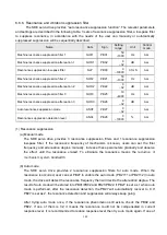
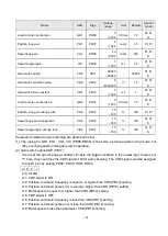
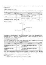
The states of parameters change
Name
CDP OFF CDP ON CDP OFF
Load to motor inertia ratio
10
→
20
→
10
Position loop gain
100
→
80
→
100
Speed loop gain
500
→
600
→
500
Speed integral gain
100
→
150
→
100
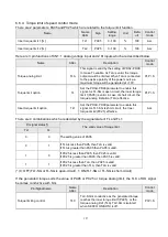
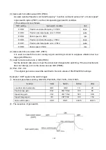
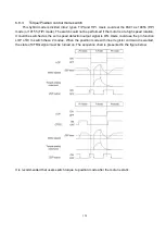
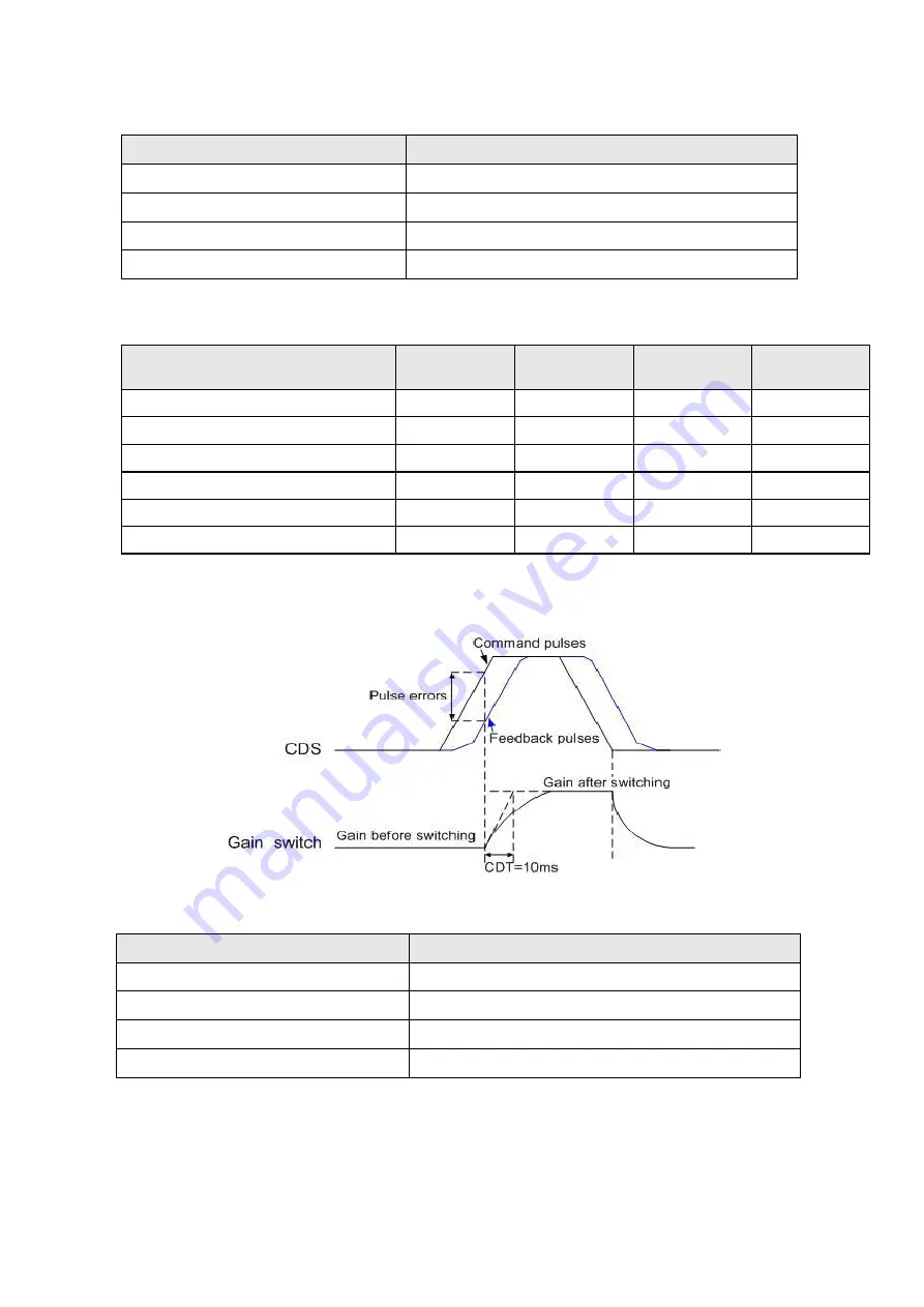
Example 2: Trigger condition of position command pulse error.
①
.
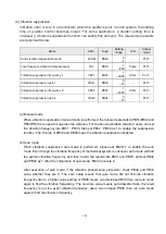
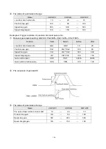
Relevant parameters setting: GD2=20, PG2=80%, VG2=120%, VIC2=150%
Function
Initial
Switch
Before
After
Load to motor inertia ratio
GD1
GD2
10
20
Position loop gain
PG1
PG1*PG2
100
80
Speed loop gain
VG1
VG1*VG2
500
600
Speed integral gain
VIC
VIC*VIC2
100
150
Gain switch option
CDP
PB11
0003h
0003h
Gain switch condition value
CDS
CDS
100
100
②
.
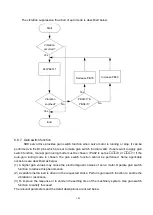
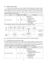
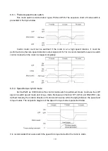
The sequence of gain switch
③
.
The states of parameters change
Name
CDP OFF CDP ON CDP OFF
The ratio of load inertia to motor shaft
10
→
20
→
10
Position loop gain
100
→
80
→
100
Speed loop gain
500
→
600
→
500
Speed integral gain
100
→
150
→
100
Summary of Contents for SDE Series
Page 13: ...5 1 6 Function block diagram ...
Page 26: ...18 3 3 3 CN1 pin name list ...
Page 223: ...215 SME L040 SME L075 SME L100 SME L150 ...
Page 224: ...216 SME L200 SME L300 SME M100 SME M150 Continuous running range ...
Page 227: ...219 ...
Page 231: ...223 4 Wiring example with peripheral equipment CN2 Encoder socket ...
Page 242: ...234 12 4 Version information Version V1 01 Issue date Aug 2017 Proofreader Yaochou Shu ...

