155
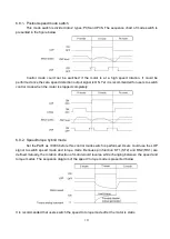
6.8.1. Position/speed mode switch
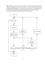
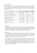
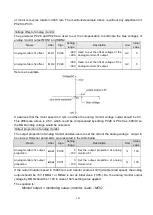
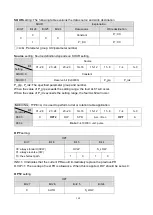
This mode switch is divided into 2 types: Pt/S and Pr/S. The sequence chart of mode switch is
presented in the figure below.
Control mode could not be switched if the motor is at a high speed rotation. It could be
performed once the zero speed detection output signal is ON. Yet it is recommended for users to switch
control mode when the motor is stopped completely.
6.8.2. Speed/torque hybrid mode
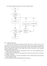
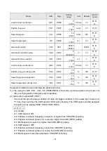
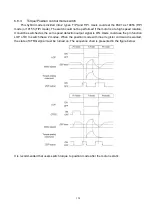
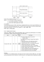
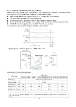
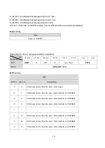
Set the PA01 as 1003h before this control mode switch is performed. Users could use the LOP
signal to switch speed mode and torque mode. Because pin function ST1 (ST2) and RS2 (RS1) are
defined mutually, the rotation direction of motor would reverse while changing between the speed and
torque modes. The sequence diagram of the speed / torque mode is presented below.
It is recommended that users switch the speed to torque mode after the motor is static.
Summary of Contents for SDE Series
Page 13: ...5 1 6 Function block diagram ...
Page 26: ...18 3 3 3 CN1 pin name list ...
Page 223: ...215 SME L040 SME L075 SME L100 SME L150 ...
Page 224: ...216 SME L200 SME L300 SME M100 SME M150 Continuous running range ...
Page 227: ...219 ...
Page 231: ...223 4 Wiring example with peripheral equipment CN2 Encoder socket ...
Page 242: ...234 12 4 Version information Version V1 01 Issue date Aug 2017 Proofreader Yaochou Shu ...

