169
SOUR
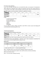
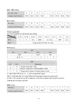
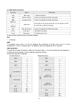
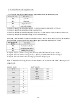
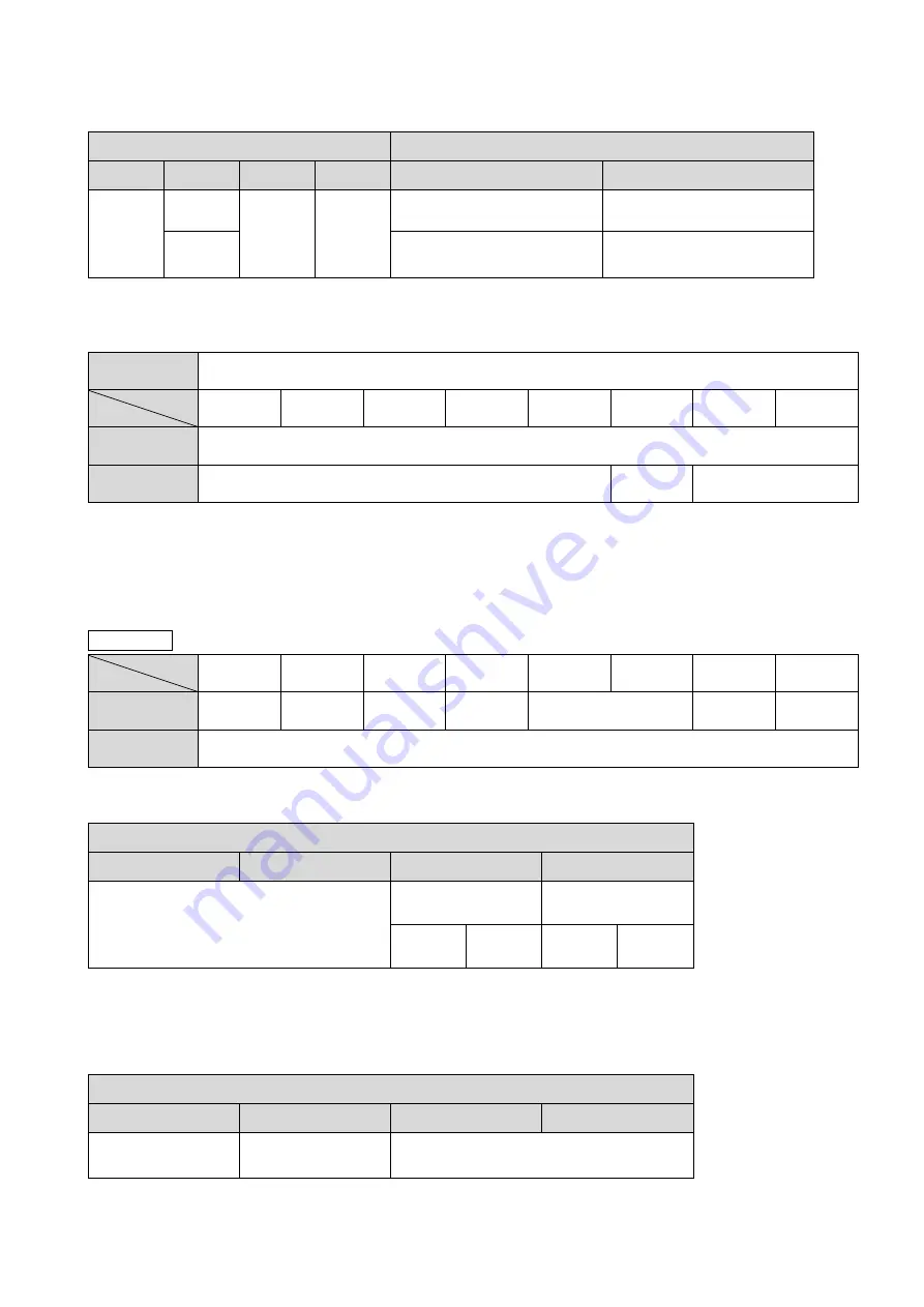
setting: The following table explains the data source and write destination
SOUR
Explanation
Bit 27
Bit 26
Bit 25
Bit 24
Data source
Write destination
X
0
X
X
Constant
P
□
XX
1
P
□
XX
P
□
XX
□
=A~G, Parameter group, XX=parameter number
Source
setting: Source definition depends on SOUR setting.
Source
Bit
31~28
27~24
23~20
19~16
15~12
11~8
7~4
3~0
SOUR=0
Constant
SOUR=1
Reserve bit (0x00000)
P_grp
P_idx
P_grp, P_idx: The specified parameter group and number.
When the value of P_grp exceeds the setting range, the fault AL61 will occur.
When the value of P_idx exceeds the setting range, the fault AL62 will occur.
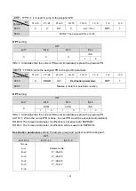
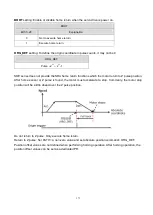
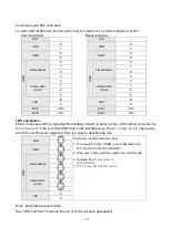
INDEXING : TYPE=A, it is used to perform turret or rotation table application
Bit
31~28
27~24
23~20
19~16
15~12
11~8
7~4
3~0
PE03
X
OPT2
DLY
SPD
Acc. / Dec.
OPT
A
PE04
Data
: 0~4194303, unit: pulse
OPT
setting:
OPT
Bit 7
Bit 6
Bit 5
Bit 4
00: always forward (CCW)
01: always reverse (CW)
10: the shortest path
OVLP
S_LOW
1
0
1
0
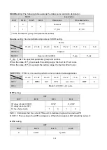
INS=1: It indicates that the current PR would immediately replace the previous PR.
OVLP=1: The overlap of next PR is allowance. When this is applied, DLY should be set as 0.
OPT2
setting:
OPT
Bit 27
Bit 26
Bit2 5
Bit 24
X
AUTO
S_LOW
Setting
Parameter
Summary of Contents for SDE Series
Page 13: ...5 1 6 Function block diagram ...
Page 26: ...18 3 3 3 CN1 pin name list ...
Page 223: ...215 SME L040 SME L075 SME L100 SME L150 ...
Page 224: ...216 SME L200 SME L300 SME M100 SME M150 Continuous running range ...
Page 227: ...219 ...
Page 231: ...223 4 Wiring example with peripheral equipment CN2 Encoder socket ...
Page 242: ...234 12 4 Version information Version V1 01 Issue date Aug 2017 Proofreader Yaochou Shu ...

