60
4.9. Startup in various control modes
Make a startup in accordance with section 4.1.
4.9.1. Startup in position control mode
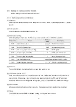
(1) Power on
Switch off SON before the servo drive has powered on. After power on, the display shows
“r”. (Motor
speed)
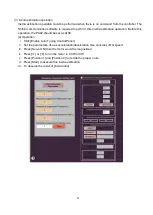
(2) Test operation
Confirm the servo motor status with a JOG test.
(3) Parameters setting
After wiring for position mode, the following parameters should be set for this operation.
Parameter
Name
Setting
value
Description
PA01
Control mode option
□□□
0
Position control mode
PA02
Gain tuning mode option
0002
Auto-gain tuning mode 1
PA03
Auto-tuning response level setting
0012
Middle rigidity
PA06
Electronic gear numerator
1
Set the numerator as
“1”
PA07
Electronic gear denominator
1
Set the denominator as
“1”
PA13
Command pulse option
Setting corresponds with user
‟s signals.
PD15
Digital input filter time option
□□□
2
Filter time constant is
“4mS”
(4) Servo on
Turn on SON then the motor shaft is locked and ready to run.
(5) Command pulses input
First, make the servo motor run at a low speed and confirm the direction and operation of
servo motor. If the pulse train commands are open collector type, PP and NP are input
terminals. When line driver signals are applied, please choose PP-PG or NP-NG wirings.
(6) Home return
After executing this function, check whether the designate origin position has reached.
(7) Stop
Turn off SON or make EMG activated to stop running the servo motor.
Summary of Contents for SDE Series
Page 13: ...5 1 6 Function block diagram ...
Page 26: ...18 3 3 3 CN1 pin name list ...
Page 223: ...215 SME L040 SME L075 SME L100 SME L150 ...
Page 224: ...216 SME L200 SME L300 SME M100 SME M150 Continuous running range ...
Page 227: ...219 ...
Page 231: ...223 4 Wiring example with peripheral equipment CN2 Encoder socket ...
Page 242: ...234 12 4 Version information Version V1 01 Issue date Aug 2017 Proofreader Yaochou Shu ...

