Parameter Description
Parameters
108
display the FM correction index. Press
to adjust the value of P.187. The screen will
display a progressively increase of the FM correction index. Press
SET
for more than 1
second, and the pointer will move upward. Press
to adjust the value of P.187
downward, and the screen will display a progressively decrease of the FM correction
index. Press
SET
for more than 1 second and the pointer will move downward.
• When P.64 = 1 and P.74 is set to 1~9000, the external terminal HDO select the frequency
multiplication output function which maximum frequency is 100 kHz.
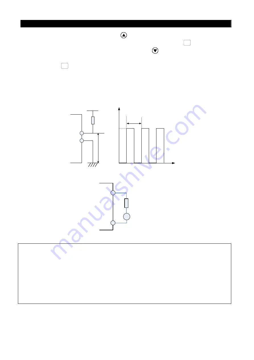
• When P.64=1, P.74 is set at 5 and the instantaneous frequency of operation is 20Hz, the
output pulse wave between terminal HDO and terminal SD is as following diagram:
R>4.7k
DC24V
HDO
SD
Vo
T
Vo
10ms
24V
0
Figure 5
HDO
A
PC
R=18~22k
Ω
1mA
Figure 6
Note: 1. Whether the terminal AM1 or the terminal HDO is valid is determined by both the toggle switch
SW12 on control board and the parameter P.64. The factory default value is that the terminal
AM1 is valid.
2. When P.64=1 or SW12 is set to HDO, the terminal AM1 is invalid.
3. When P.64 = 0, 2, 3 or SW12 is set to AM1, the terminal HDO is invalid.
4. Functions of FM and frequency multiplication share a hardware terminal. Changing the value of
P.74 can switch the function between FM and frequency multiplication.
5. When P.64=1 and P.74=1, the output is one time of the running frequency. And the inverter can
provide the output from 1~650Hz which precision is 1%. The bigger the value of P.74 and the
bigger the running frequency is, the worse the precision will be.


