Parameter Description
Parameters
120
5.39 Multi-function Terminal Function Selection
(P.80~P.84, P.86, P.126, P.550)
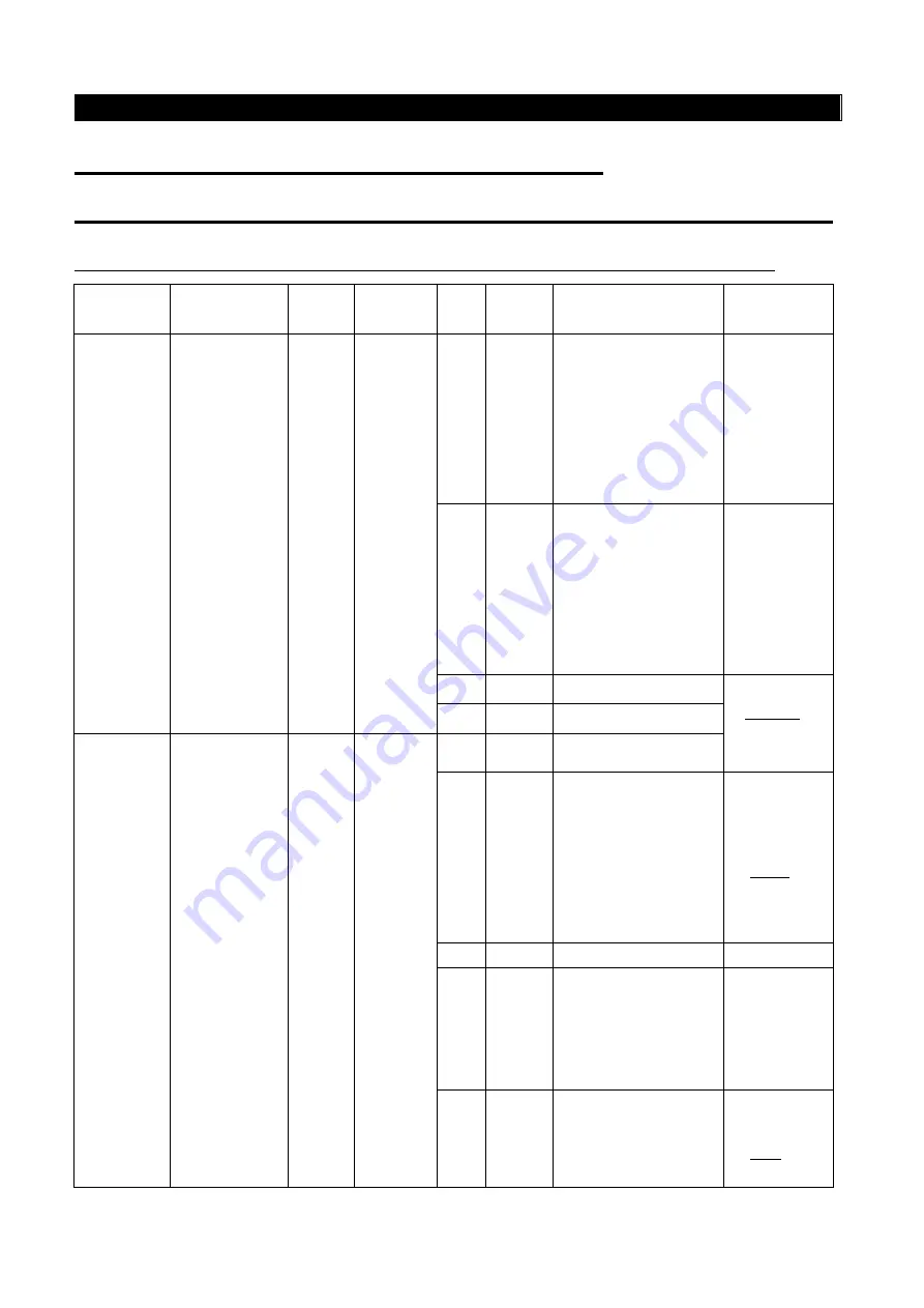
P.80~P.84, P.86, P.126, P.550 “Multi-function terminal function selection”
Relevant
Parameters
Corresponding
terminal
Factory
setting
Setting
range
Value
Function
name
Function description
Remarks
80
M0
2
0~40
,
43~53
,
55~56
0
STF
In “external mode”,
“combined mode 1”,
or “combined mode
3”, and when STF is
on, the inverter runs
forward.
In
programmed
operation
mode, it is
used as the
start signal
terminal.
1
STR
In “external mode”,
“combined mode 1”,
or “combined mode
3”, and when STF is
on, the inverter runs
forward.
In
programmed
operation
mode, it is
used as the
pause signal
terminal.
2
RL
Multi-speed
Please refer
toP.4~P.6 for
multi-speed
instruction.
3
RM
Multi-speed
81
M1
3
0~40
,
43~53
,
55~56
4
RH
Multi-speed
5
AU
In “external mode”,
"combined mode 2”
or “combined mode
4”, the inverter target
frequency is set by
the signal input
across terminal 4 -5.
Refer
to P.39
6
OH
(Note 3)
7
MRS
When MRS is “turned
on”, the output of the
inverter will be
terminated
immediately.
8
RT
When RT is “on”, the
characteristics are
the same as the
second function.
Refer
to P.44


