Parameter Description
Parameters
126
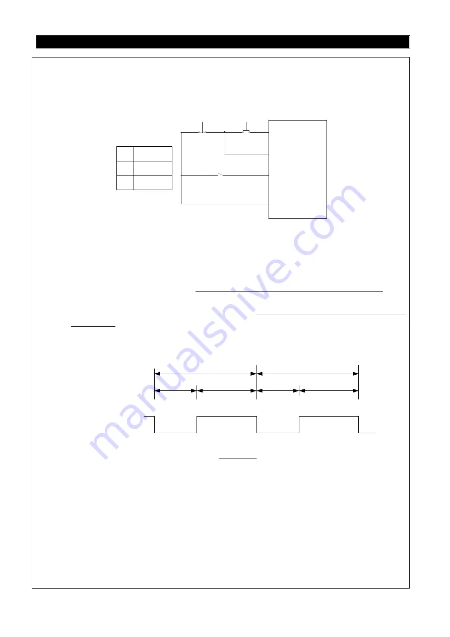
(4). Three-wire control mode 2 (with self-maintenance function): K1 is for the STOP function that
is normally close. When it is open, the inverter will stop. K2 is the RUN signal that is normally
open. It indicates that pulse signal is active, i.e., jog is valid. For the direction changing signal
(STF/STR), the parameter corresponds to the external terminals is 39. When changing the
direction, stop the inverter first, RUN the inverter before activating it.
STOP (P. 8X=31)
K0
K2
K1
STF/STR (P.8X=29)
RUN (P.8X=28)
Operating
Instruction
SD
K0
1
0
Run Forward
Run Reverse
5. In “external mode" and when PO is “on”, select the programmed operation mode. At this stage,
the STF terminal is the source of the start signal. When STF is “on”, the inverter begins to run in
the programmed operation mode at the first section. When STF is "off”, the invert stops running,
and STR becomes the pause signal source. When STR is “on”, the operation will be
suspended. When STR is “off”, the operation sill be continued (continues from the suspended
section).For details, please refer to P.100~P.108, P.111~P.118, P.121~P.123, P.131~P.138.
6. In the external mode, the manual operation cycle mode is selected when MPO is “on”. For details
on parameter and operation, please refer to P.100~P.108, P.111~P.118, P.121~P.123,
7. PWM setting frequency (P.550 = 41): the inverter will measure and calculate the time of ON and
OFF every PWM period as the frequency reference. (The PWM period within 0.9ms ~ 1100ms
admissible)
PWM period
ON(Tr)
OFF(Tr)
ON(Tr)
OFF(Tr)
The resolution between
PWM signal and
frequency command
Frequency command
(
Hz
)
=
ON time
PWM period
× upper limit frequency P.1 (Hz)
PWM period
The function is only valid for the terminal HDI. Near the minimum frequency and the maximum
frequency, the precision of the output frequency will reduced relative to the input signal, please
avoid using on the occasion needed rigorous frequency control.
8. When P.550=57 and the toggle switch HDI is set to HDI, the high-speed pulse mode is valid. As
the high-speed pulse input terminal, HDI is used to given the target frequency, please refer to
P.522.
9. When P.550 = 54, the toggle switch SW11 must be switched to HDI. The function is under the
tension control mode and it is used to calculate the turns of the winding shaft rotation when
calculating the curling radius with the sickness accumulation method.
10. External terminals switch “speed/torque control”: when switch speed-control to torque-control,


