Parameter Description
Parameters
132
• When P.122 is 1~8, it is the initial sectional speed at the beginning of the cycle.
For example: When P.122=3, the inverter will run circularly from the third section to the
eighth section after it finishes its running from the first section to the eighth
section.
• When P.123 = 0, the acceleration time is determined by P.7, and the deceleration time is
determined by P.8.
• When P.123 = 1, the acceleration time and deceleration time are both determined
by P.111~P.118.
2. Manual operation cycle mode
• Insert an impulse type switch between M0 and SD.
• After turning on the power, set P.80=35 according to terminals wiring. Set corresponding
parameter P.80 to 35.The inverter is on standby at this point.
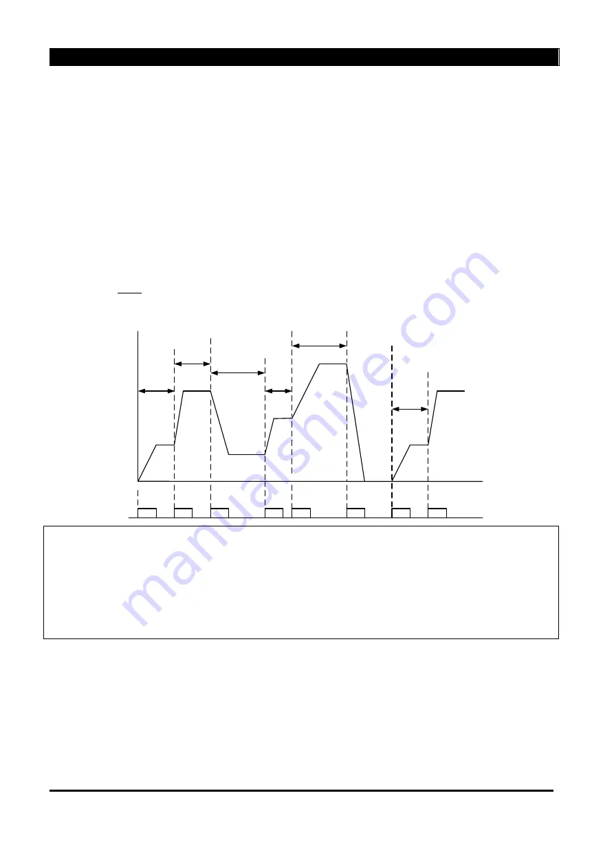
• The mode of operation is shown in the figure below:
frequency
RL
ON
ON
ON
ON
ON
ON
ON
ON
……
P.131
P.132
P.133
P.134
P.135
P.131
P.132
0
Note: 1. The inverter can run eight levels of speed in the procedure, and the frequency is determined
by P.131~P.138.
2. If there is any section set to zero, the inverter will be on standby in this section. In other
word, P.131 has to be nonzero when this mode is selected. Like the figure above, regardless of
the value of P.137 and P.138, the inverter sills stop when the switch is pressed for the sixth time.
3. The rotation of the manual operation cycle mode is unilateralism. It has nothing to do with P.121
or the signals of STF and STR.
5.46 Operation Panel Monitoring Selection (P.110)


