Parameter Description
Parameters
138
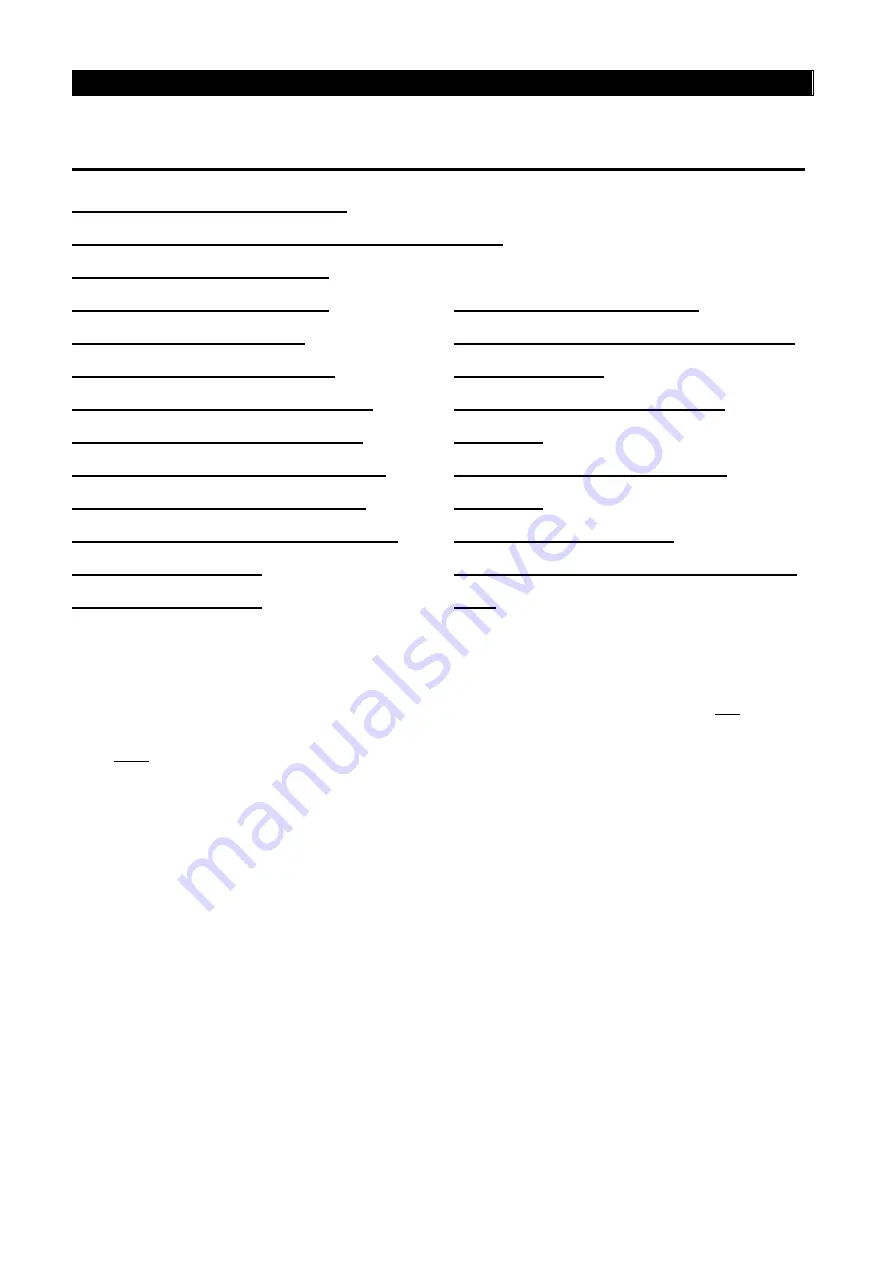
5.54 PID Parameters 1 (P.170~P.183, P.223~P.225, P.241)
P.170 “PID function selection”
P.171 “PID feedback control method selection”
P.172 “PID proportion Gain”
P.172 “PID proportion Gain”
P.173 “PID Integral Gain”
P.174 “PID Differential Gain”
P.175 “Abnormal deviation level”
P.176 “Exception duration time”
P.177 “Exception handling mode ”
P.178 “Sleep detects deviation”
P.179 “Sleep detects duration time”
P.180 “Revival level”
P.181 “Outage level”
P.182 “Integral upper limit”
P.183 “Deceleration step length with
stable pressure”
P.223 “Analog feedback bias
pressure”
P.224 “Analog feedback gain
pressure”
P.225 “Panel reference”
P.241 “Sampling period controled by
PID”
● During the operation of PID control, the frequency displayed on the screen is the output
frequency of the inverter.
● The output frequency during the operation is similar to output frequency during the normal
operation. They are both limited within the upper limit P.182 and the lower limit P.2.
● For input signal filtering of terminal 2-5 and terminal 4-5, please refer to the instructions
for P.60.
● The sketch map of PID function is shown as follows:


