Parameter Description
Parameters
141
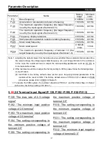
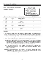
Note: 1.The range of default setting is 0.1~5V. If there is a mismatch between the default setting range
and the user’s range,
P.223 and P.224
can be set and P.170 must be set at last to unify the range.
2. If take terminal 4-5 as the target or feedback source, please must set the value of P.17 at first, and
determine whether terminal 4-5 signal is voltage or current according to the switch SW2, and then
take other operations.
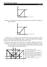
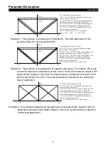
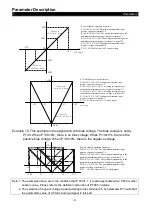
Example: When the 0~7V feedback signal is given by terminal 2-5 or 1-5:
1). When P.171=0 (negative feedback control), P.223 = 0.1 / 7 * 100.0 = 1.4
P.224 = 5 / 7 * 100.0 = 71.4
2). When P.171=1 (positive feedback control), P.223 = (7 - 0.1) / 7 * 100.0 = 98.6
P.224 = (7- 5) / 7 * 100.0 = 28.6
By setting P.223 and P.224 as the above calculated value, and then setting P.170 at
1, the revised range is 0~7V.
Example: When the 0~20mA feedback signal is given by terminal 4-5:
1). When P.171=0 (negative feedback control), P.223 = 4 / 20 * 100.0 = 20.0
P.224 = 20 / 20 * 100.0 = 100.0
2). When P.171=1 (positive feedback control), P.223 = (20 – 4) / 20 * 100.0 = 80.0
P.224 = (20 – 20) / 20 * 100.0 =0
By setting P.223 and P.224 as the above calculated value, and then setting P.170 at 2,
the revised range is 0~20mA.
2. When the feedback signal need to be revised by the user:
Please adjust the feedback signal to a certain value and then calculate the proportion of
the value to the feedback range, then write the proportion value into P.223.
After that, adjust the feedback signal to a new value and then calculate the proportion of
the value to the feedback range, then write the proportion value into P.224.
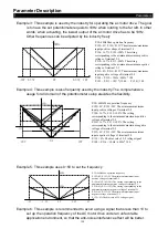
Example: When the user’s feedback range is 0~10kg:
When the feedback signal is adjusted to 4kg, P.223 = (4/10) * 100.0 = 40,
When the feedback signal is adjusted to 6kg, P.224= (6/10) * 100.0 = 60
Note: The actual feedback signal must be connected and the value of P.170 must be set before revising
like this.
• The instruction for the target pressure given by external analog terminal:
1.
When the target value is set by terminal 2-5 (P.500=3)
When P.73 = 0, the given range is 0~5V corresponding to 0~100%;
When P.73 = 1, the given range is 0~10V corresponding to 0~100%.
2.
When the target value is set by terminal 4-5 (P.501=3)
The given range is 4~20mA corresponding to 0~100%.
Example: Set P.170 = 1
,
P.171 = 0.
It indicates that the PID target value is given by the current of terminal 4-5 (4~20mA).
If 8mA is given by the user, the corresponding given proportion is (8-4)/ (20-4) * 100.0= 25.0.


