Parameter Description
Parameters
144
5.55 4-5 Terminal Disconnection Handling Function (P.184)
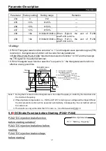
P.184 “4-5 terminal disconnection handling”
Parameter
Factory setting
Setting range
Remarks
184
0
0~3
---
<Setting>
• When P.184=0, the inverter will decelerate to 0Hz when disconnected. After reconnecting
the inverter, the inverter will accelerate to the corresponding frequency.
• When P.184=1, the inverter will decelerate to 0Hz when disconnected. After reconnecting
the inverter, the inverter will accelerate to the corresponding frequency. Meanwhile, the
multi-function output terminal will set off the alarm. Reconnection will clear the alarm.
• When P.184=2, the panel will display the “AEr” alarm when disconnected. The inverter will
stop immediately. Reset to clear the alarm.
• When P.184=3, the inverter will run continuously according to the frequency reference
before the disconnection. The multi-function output terminal will set off the alarm.
Reconnect to clear the alarm.
Note: Please refer to P.40, P.129 and P.130. For wiring, please refer to Section 3.5.
5.56 The Proportion Linkage Function and The Auxiliary Frequency
Function (P.185, P.240)
P.185 “Proportion linkage gain”
P.240 “Auxiliary frequency function”
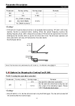
Parameter
Factory
setting
Setting
range
Remarks
185
0%
0~100%
The function is used to multiply the setting frequency by the
external analog input terminal.
When many inverters run proportionally, the reference
frequency from the master inverter to the slave inverter can be
fine tuned effectively with the function.
When P.185 = 0, the function is invalid.
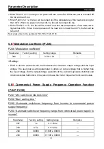
240
0
0~9
0 No auxiliary frequency function is available.
1
operation frequency = basic fre auxiliary
frequency (given by the 2-5 terminal)
2
operation frequency = basic fre auxiliary
frequency (given by the 4-5 terminal)
3
operation frequency = basic frequency - auxiliary
frequency (given by the 2-5 terminal)


