Parameter Description
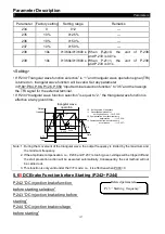
Parameters
148
P.513 “The maximum input negative
voltage of terminal 2-5”
Related parameters
P. 73
“
The selection of voltage
signal across terminal 2-5
”
P. 80~P. 84 , P. 86
“
Multi-function terminals selection
”
P.38
“
The maximum output
frequency of terminal 2-5
”
P.500
“
Function selection of terminal 2-5
”
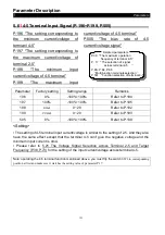
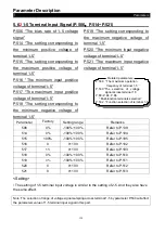
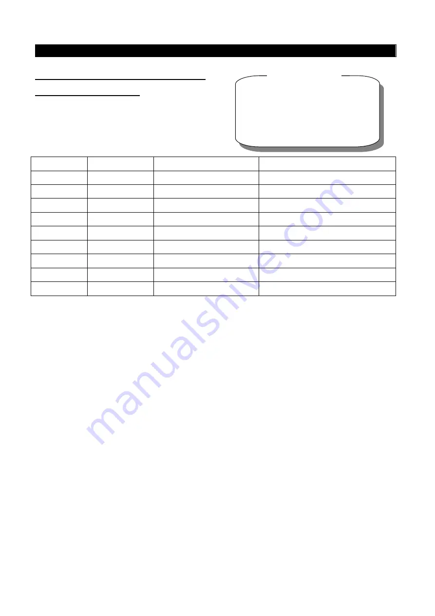
Parameter
Factory setting
Setting range
Remarks
139
0.0%
-100.0%~100.0%
---
192
0
0~10
---
193
5V
0~10
---
194
0.0%
-100.0%~100.0%
---
195
100.0%
-100.0%~100.0%
---
510
0.0%
-100.0%~100.0%
---
511
0.0%
-100.0%~100.0%
---
512
0
0~10
---
513
0
0~10
---
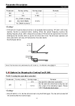
<Setting>
1.
The parameters above define the relationship between analog input voltage and the
setting value what analog input represents. When the analog input voltage exceeds the
maximum or minimum range of the setting value, the excess will be computed as the
maximum or minimum input.
2
.
There are two setting order when the maximum or minimum percentage is set:
a. If the users hope to adjust the analog input magnitude to correspond to a certain
proportion relationship, the analog input need to be adjusted before setting the
corresponding proportion parameters. Now the inverter will compute automatically
without setting the voltage parameters. Please refer to the example 1.1.
b. If the users skip adjusting analog input to set the proportion relationship, the
proportion parameter should be set before setting the voltage parameters. Please
refer to the example 1.2.
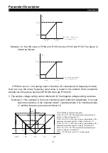
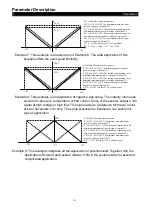
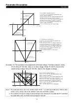
Example 1.1: Adjust the analog input voltage to the minimum value A and set the
parameter P.194. Then adjust the input voltage to the maximum value B and set
the parameter P.195. The figure is shown as follows:


