Parameter Description
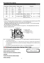
Parameters
149
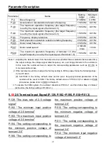
The value
of A
The value
of B
P.194
P.195
The signal magnitude
of terminal 2-5
%
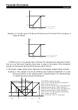
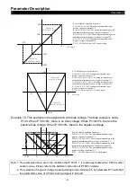
Example 1.2: Set the value of P.194 and P.195, then set P.192 and P.193. The figure is
shown as follows:
P.192
P.193
P.194
P.195
The signal magnitude
of terminal 2-5
%
If P.500 is set at 1, the analog input of terminal 2-5 corresponds to frequency function,
that is to say the actual frequency input value is equal to the product of the proportion
worked out in the above figure and P.38 (the bias rate P.139 is 0).
3. The positive voltage setting can be referred to for the negative voltage setting, as above.
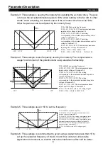
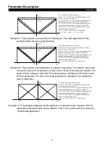
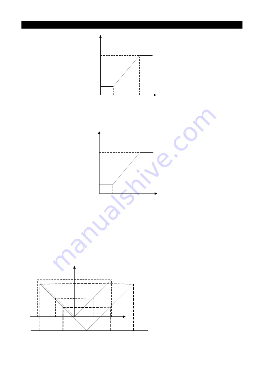
Example 2: This example is the most commonly used method of adjustment. It is used
when the inverter is in the “external mode", “combined mode 2”or “combined mode
4”, and the frequency are set by terminal 2-5.
60
60
Hz
Hz
10
10
V
V
-
-
10
10
V
V
30
30
Hz
Hz
5
5
V
V
-
-
5
5
V
V
0
0
V
V
P.38=60Hz Max operation frequency
P.192=0V, P.193=10V The minimum/maximum input
positive voltage of terminal 2-5
P.194=0%, P.195=100% The setting corresponding to the
minimum/maximum positive voltage of terminal 2-5
P.510=0%, P.511=100% The setting corresponding to the
minimum/maximum negative voltage of terminal 2-5
P.512=0V, P.513=10V The minimum/maximum input
negative voltage of terminal 2-5
P.139 = 0% The bias rate of 2-5 voltage signal


