Shihlin Inverter Introduction
Inverter Introduction
18
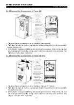
3.4.3 Names of the Components of Frame A/B
1. The above figure corresponds to all the models of frame A and B.
2. Push down the latch on the top cover and pull the latch toward the front of the inverter to
remove the top cover.
3. “Wiring Outlet” is designed for fixing and protecting the lead wire. When wiring, the lead
wire must passed through the “wiring outlet” and then connected to the terminals. Use
cable ties to fix the wires in a bundle.
3.4.4 Names of the Components of Frame D/E/F/G
1. The above figure corresponds to all the models of frame D, E, F and G.
2. Push down the latch on the top cover and pull the latch toward the front of the inverter to
remove the top cover.
3. “Wiring Outlet” is designed for fixing and protecting the lead wire. When wiring, the lead
wire must passed through the “wiring outlet” and then connected to the terminals. Use
cable ties to fix the wires in a bundle.


