Shihlin Inverter Introduction
Inverter Introduction
32
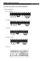
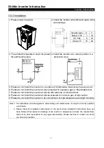
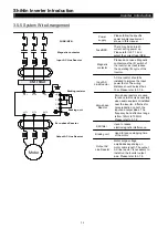
6. “Pressing connection terminals with insulated sleeve” shall be utilized for the wiring at the
power source side and the load side.
7. In a short period after the power supply is shut off, high voltage still exists between
terminals (+/P)-(-/N), so do not touch them within 10 minutes to avoid electric shock.
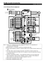
Control circuit wiring arrangement:
1. For wiring of signal input, use only “insulated wires" with the “metal mesh" corrected
grounded.
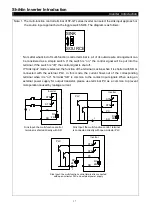
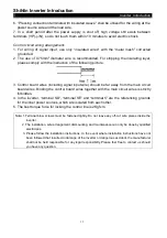
2. The use of 0.75mm
2
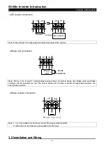
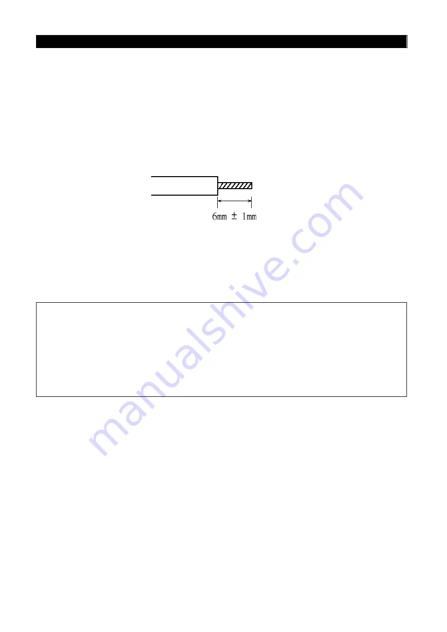
diameter wire is recommended. For stripping the insulating layer,
please comply with the instruction of the following picture.
3. Control board wires (including signal input wire) should be far away from the main circuit
board wires. Binding the control board wires together with the main circuit wires is strictly
forbidden.
4. In the inverter, “terminal SD”, “terminal SE” and “terminal 5” are the referencing grounds
for the inner power sources, which are isolated from each other.
5. The best torque force for locking the control line is 2Kgf.cm.
Note: 1.Terminal blow screws must be fastened tightly. Do not leave any off-cut wire pieces inside the
inverter.
2. The installation, wire arrangement, dismounting, and maintenance can only be done by qualified
electricians.
3. Please follow the installation instructions. In the event where installation instructions have not
been followed that resulted in damage of the inverter or dangerous accident, the manufacturer
shall not be held responsible for any legal responsibility. Please feel free to contact us should
you have any question.

