Parameter Description
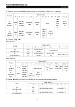
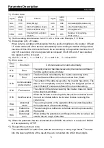
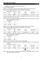
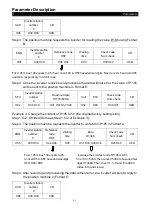
Parameters
72
Acceleration slope
Time
Output frequency
f0
f2
f3
Note: this pattern can effectively reduce motor vibration during the acceleration / deceleration, and thus
prevent the belts and gears from broken.
•
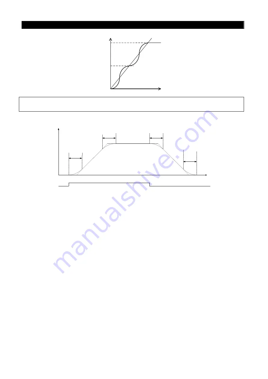
When P.29=3, “S pattern acceleration /deceleration curve 3”
Output
frequency
time
Starting
signal
ON
OFF
P.255
P.256
P.257
P.258
1)
The parameters P.255, P.256, P.257 and P.258 are used to start the inverter gradually
without impact. And varying degrees of S pattern acceleration/deceleration curve are
adjusted by the values. When the S pattern acceleration/deceleration curve is
started, the inverter will accelerate/decelerate with different speed according to the
primary acceleration/deceleration time.
2)
When S pattern acceleration/deceleration curve 3 is selected, the acceleration/
deceleration time will be longer, as follows.
3)
When the selected acceleration time (P.7 or P.44)
≥
P.255 and P.256, the actual
acceleration time is as follows:
The actual acceleration time
=
The selected acceleration time
+
(P.255 + P.256)/ 2
4)
When the selected deceleration time (P.8 or P.45)
≥
P.257 and P.258, the actual
deceleration time is as follows:
The actual deceleration time
=
The selected deceleration time
+
(P.257 + P.258)/ 2
Example
:
When the parameters are initial value (60 Hz system), the actual acceleration
time from 0Hz to 60Hz in accordance with S pattern acceleration/deceleration curve 3 is
as follows:


