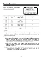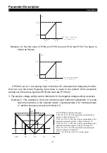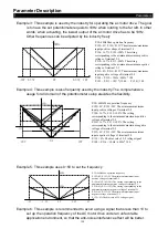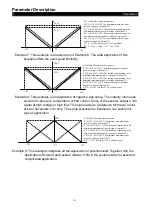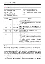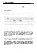
Parameter Description
Parameters
162
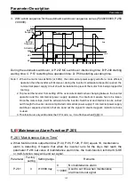
3. With action sequence for the automatic switchover sequence series (
P.249≠99999, P.250
≠ 99999).
STF
time
A
A
B
C
D
A
A
B
C D
time
P.249
P.250
MC2
MC1
Setting
frequency
Output
frequency
Actual motor
speed
During the automatic switchover, A: P.247 MC switchover interlocking time; B: P.248 starting
waiting time; C: P.57 restarting free operation time; D: P.58 restarting elevating time.
Note: 1. When the motor runs at 50Hz (or 60Hz), the commercial power supply will offer a more efficient
operation than the inverter will. Moreover, during the inverter maintenance/inspection period, the
commercial power supply circuit should be installed to prevent the motor from being stopped for
too long.
2. To prevent the inverter from setting off the over-current alarm when changing between the inverter
operation and the commercial power supply operation, the interlock measure has to be taken.
Once the motor stops, it will be activated via the inverter. Switchover and interlock can be carried
out through the inverter and a complicated commercial power supply if commercial power supply
switchover sequence function that can send out the signal for electromagnetic contactor actions
is used.
3. This function is only valid under the V/F mode; i.e., it is effective when P.300=0.
5.6
9
Maintenance Alarm Function (P.261)
P.261 “Maintenance Alarm Time”
● When Multi-function output terminal (P.40, P.85, P.129, P.130) equals 18, maintenance
alarm is detecting. It means that when the inverter runs for the days that reach the
parameter P.261 set value of maintenance alarm time, the multi-function terminal SO-SE
or multi-function relay will send out signal.
Parameter
Factory
setting
Setting range
Remarks
P.261
0
0~9998 day
0
No maintenance alarm
1~9998
Used to set time when maintenance
alarm sends out signal

