Parameter Description
Parameters
172
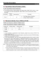
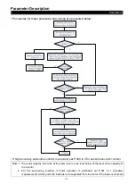
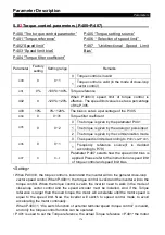
stopped, the motor parameter will carry out auto-tuning. Then press
FWD
or
REV
on the keyboard
panel for the inverter to automatically calculate the following parameter: P.308~P.312.
• The users can use the motor's nameplate to calculate the two parameters. The motor
nameplate parameters used in the calculation are: rated voltage U, rated current I, rated
frequency
f
and power factor
η
.
• The calculation of motor idling excitation current and of motor mutual induction is presented
below: L
6
is motor leakage induction.
Idling current:
2
0
1
η
−
×
=
I
I
Mutual inductance calculation:
δ
π
L
I
f
U
L
m
−
⋅
⋅
⋅
=
0
3
2
0
I
is the idling current, whereas
m
L
is mutual inductance,
δ
L
is leakage inductance.
Note: 1. When the inverter is used with a motor of a different level, verify the input motor’s nameplate
parameter P.302~P.307.The vector control method is heavily dependent upon motor parameters.
To achieve a good control performance, the controlled motor’s correct parameters have to be
acquired.
2. When any or many values of P.302~P.312 are manually revised, perform the function of P.997 to
reload the new values of the parameters.
5.7
9
Gain Adjustment at Speed Control (P.320~P.325)
P.320 “Speed control proportion
coefficient 1”
P.321 “Speed control integral
coefficient 1”
P.322 “Switching frequency 1”
P.323 “Speed control proportion
coefficient 2”
P.324 “Speed control integral
coefficient 2”
P.325 “Switching frequency 2”
Parameter
Factory setting
Setting range
Remarks
320
100%
0~2000%
---
321
0.3s
0~20s
---
322
5.00HZ
0.00~P.325
---
323
100%
0~2000%
---
324
0.3s
0~20s
---
325
10.00Hz
P.322~the largest output
frequency
---
<Setting>
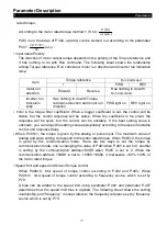
• P.320 and P.321 are the PI adjusting parameter when the running frequency is less than the
switching frequency 1 (P.322). P.323 and P.324 are the PI adjusting parameter when the
running frequency is greater than the switching frequency 2 (P.325). When the running

