Primary Operation
Primary operation
43
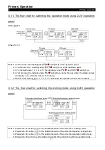
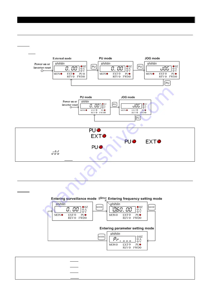
4.1.1 The flow chart for switching the operation mode using DU01 operation
panel
When P.79=0:
When P.79 = 1:
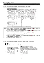
Note: 1. In “PU mode,” the indicating lamp
will light up on the operation panel.
2. In “external mode,” indicating lamp
will light up on the operation panel.
3. In “combined mode 1, 2, 3, 4, or 5," the indicating lamp
and
will light up.
4. In “JOG mode,” the indicating lamp
will light up, and at the same time, the display screen
will display
while the motor is not running.
5. No flow chart when P. 79=2, 3, 4, 5, 6, 7 or 8 because the operation mode will be constant.
4.1.2 The flow chart for switching the working mode using DU01 operation
panel
Note: 1. Please refer to section 4.1.3 for the detailed operation flow under the monitoring mode.
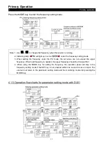
2. Please refer to section 4.1.4 for the detailed operation flow under the frequency setting mode.
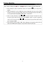
3. Please refer to section 4.1.5 for the detailed operation flow under the parameter setting mode.
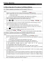
4. Please refer to Section 4.1.2 for detailed operation flow under the switching operation mode.

