106
4. Parameter description
Parameter
Note: 1. The equation for the above curve is:
2. After P.194 and P.195 are reset, the curve of P.38 is invalid.
4.52
Bias (gain) of input signal across terminal 4-5 (P.196, P.197)
P.196
“
Bias of input signal across
terminal 4-5
”
P.197
“
Gain of input signal across
terminal 4-5
”
Parameter
Factory setting
Setting range
Remarks
196
0
0~60Hz
50Hz
When P.189=1
197
60Hz
0~400Hz
When P.189=0
<Setting>
•
Emendation steps:
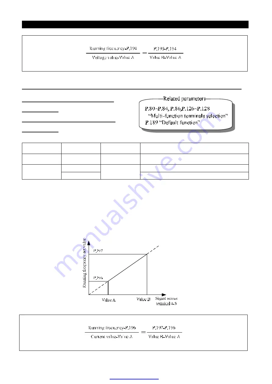
1. Make sure that the current signal is correctly put in.
2. Assume that the input current equals Value A, and the expected output frequency is 20Hz. Then
adjust the signal to Value A, and write 20 into P.196.
3. Assume that the input current equals Value B, and the expected output frequency is 60Hz.Then
adjust the signal to Value B, and write 60 into P.197.
Note: 1.
The equation for the above figure is:
2.
After P.196 and P.197 are reset, the curve of
P.39
is invalid.
PDF created with pdfFactory trial version


