50
4. Parameter description
Parameter
•
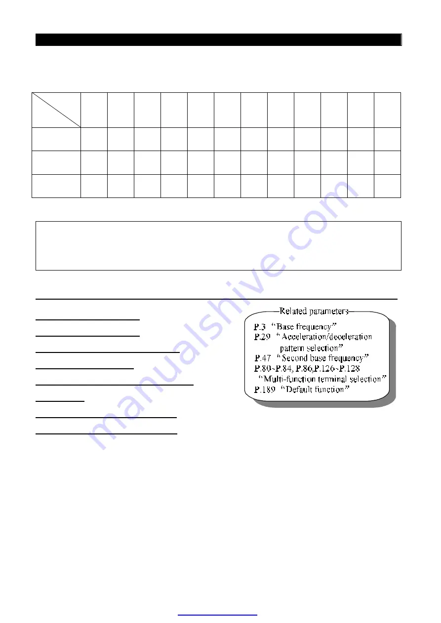
Provided that the values of P.24~P.27 and P.142~P.149 are all defaulted,
‘
3-speed operation
’
is
active. In this case, the target frequency can be set as follows (the priority for the terminals is
RL>RM>RH):
Parameter
Target
frequency
P.24=
99999
P.25=
99999
P.26=
99999
P.27=
99999
P.142=
99999
P.143=
99999
P.144=
99999
P.145=
99999
P.146=
99999
P.147=
99999
P.148=
99999
P.149=
99999
RL
(
P.6
)
○
○
○
○
○
○
○
○
RM
(
P.5
)
○
○
○
RH
(
P.4
)
○
For example: if P.26=99999, the target frequency is determined by RM (the setting value of P.5).
Note: 1. Only in
‘
external mode
’
,
‘
combined mode 2
’
or
‘
combined mode 4
’
, the multi-speed is valid.
2. RL, RM, RH and REX mentioned in this section are the function names of the
‘
multi-function control
terminal
’
. (For example: P.80=2,
RL
terminal is chosen to perform the RL function). Please refer to
P.80~P.84
、
P.86
、
P.126~P.128 for multi-function selection, and refer to section 2-5 for wiring.
4.5
“
Acceleration/ deceleration time (P.7, P.8, P.20, P.21, P.44, P.45)
P.7
“
Acceleration time
”
P.8
“
Deceleration time
”
P.20
“
Acceleration/ deceleration
reference frequency
”
P.21 Acceleration/deceleration time
increments
P.44
“
Second acceleration time
”
P.45
“
Second deceleration time
”
●
When the output frequency of the inverter is accelerated from 0Hz to P.20, the required time is
defined as
‘
acceleration time (P.7)
’
●
When the output frequency of the inverter is decelerated from P.20 to 0Hz, the required time is
defined as
‘
deceleration time (P.8)
’
.
●
P.21 is used to set the acceleration/deceleration time and minimum setting increments.
PDF created with pdfFactory trial version


