


3
3. Attach the flow calibrator bottle to the wand:
a. Remove the nozzle, cap and filter from the spray wand.
b. Mount the flow calibrator cover
to the spray wand.
c. Reinstall the nozzle, filter and
nozzle cap.
d. Screw the flow calibrator bottle
into the cover.
4. Using the flow calibrator bottle:
a. Operate the pump handle to
maintain spray system pressure as
you would when applying chemi-
cals.
b. Hold the wand at your normal
working position and spray into the bottle while walking the
distance identified in step 2 above.
c. Place the bottle on a level surface and observe the liquid
level visible through the side of the bottle. Match the liquid
level to the l/acre (liter per acre) scale on the calibration
bottle.
d. Multiply the l/acre (liter per acre) reading identified in
step 4-c by .264 to determine your application coverage rate
in gallons per acre.
e. Empty the bottle contents back into the sprayer tank.
NOTE:
For improved accuracy in calibrating your application coverage,
repeat steps 4-a through 4-e and average the results.
Carefully read the labels on chemical containers
prior to use. Chemicals are classified in four
categories of toxicity:
■
Category I, High Toxicity, Red label
■
Category II, Moderate Toxicity, Yellow label
■
Category III, Low Toxicity, Blue label
■
Category IV, Light Toxicity, Green label
There are unique handling recommendations
for each category, and you should familiarize
yourself with them.
Always wear clothing and safety equipment that
will provide appropriate protection against the
materials you are handling. Equipment may
include, but not be limited to:
■
Long sleeve shirt
■
Impermeable apron or coverall
■
Impermeable gloves and boots
■
Wide-brim hat
■
Protective mask equipped with
appropriate filters
Do not eat, drink, or smoke while handling
chemicals or while you are spraying. Always
handle chemicals in a well ventilated area while
wearing appropriate protective clothing and
safety equipment. DO NOT STORE OR TRANS-
PORT CHEMICALS WITH FOOD OR MEDI-
CINES, AND NEVER REUSE A CHEMICAL
CONTAINER FOR ANY OTHER PURPOSE.
Keep chemicals out of the reach of children,
animals, or other unauthorized people. When
not in use, store chemicals in a safe place.
Never blow through nozzles, valve, pipes or any
other component by mouth!
When handling chemicals and when spraying,
make sure you are operating in accordance with
local, state, and federal environmental protec-
tion rules and guidelines. Do not spray in very
hot or windy conditions. DO NOT POLLUTE
THE ENVIRONMENT!
After spray application, take a thoroughly
cleansing shower using plenty of water and
soap, then change into clean clothes. Protective
clothing and safety gear should also be cleaned
after each use. IN CASE OF EXPOSURE TO
DANGEROUS CHEMICALS, seek a physician
immediately and be prepared to provide the
label from the chemical container.
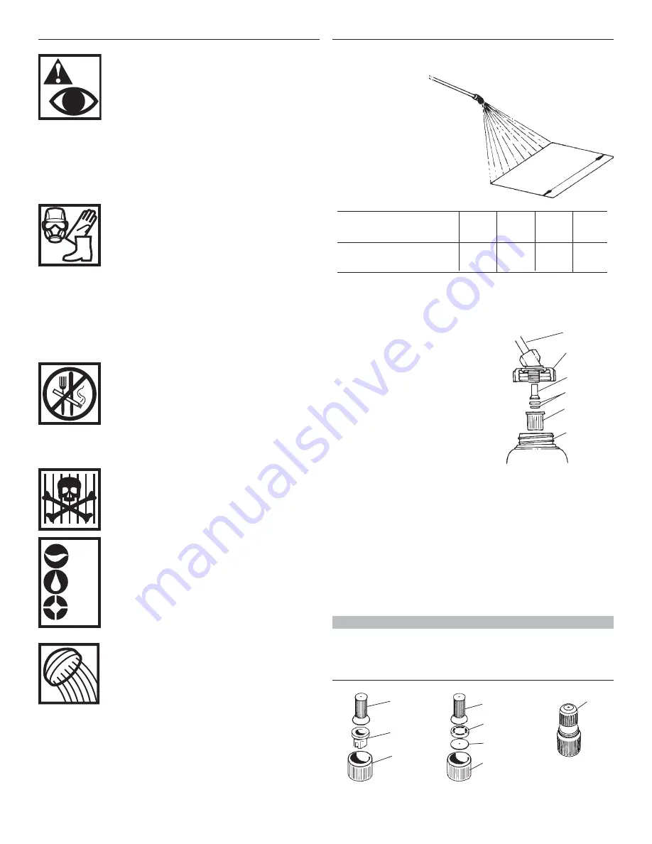
AIR
WATER
EARTH
Wand
Cover
Filter
Nozzle
Calibrator
Bottle
Band width
1.6 ft
2.3 ft
3.3 ft
4.0 ft
5.0 ft
0.5m
0.7m
1.0m
1.2m
1.5m
Distance to walk
165 ft
120 ft
80 ft
70 ft
55 ft
50.0m
35.7m
25.0m
20.8m
16.7m
Band
Width
1. Hold the wand at
the working
height and spray
a test pattern to
measure the
application band
width.
2. Based on the band width,
identify from the table
below the walking distance
required to calibrate the sprayer.
Calibrating the Sprayer
Safety Precautions
Nozzle
Cap
Tip
Filter
Swirl
Core
Disc
Filter
Tip
The spraying angle is
changed by turning
the tip
Cap
Cap
Adjustable Cone
Nozzle
Cone Nozzle
Flat Fan Nozzle
Typical Nozzle Assemblies
(Requires optional flow calibrator bottle, P/N 646901)


