background image

5

WARNING!

Remove all chemicals and wash before storing the
sprayer. Chemical products have different reactions and
can cause damage to the sprayer components and the
environment. Unidentified chemicals left in the sprayer
tank can pose a serious health threat to anyone servicing
the unit and unaware of its presence!

1. Unscrew the cylinder cap and remove

the pump chamber piston assembly
from the tank.

2. Pull the pump piston out of the pump

chamber.

3. Remove the piston cup from the pump

piston.

4. Remove the diaphragm valve from the

pump chamber.

5. Clean all parts and carefully inspect

for worn or damaged parts and replace
as necessary.

6. Reassemble in the reverse order.

NOTE:

Lubricating all moving parts with a high
quality lithium grease will ease assembly
and prolong the life of the unit.

Troubleshooting

SYMPTOM

CAUSE

REMEDY

Lack of sprayer
pressure and/or
leakage at the
cylinder.

After pumping and
pressurizing the
tank, the pump
handle rises slowly
when released
prior to being
locked in place.

Sprayer will not
hold pressure.

Tank lid difficult to
remove.

Worn or damaged
diaphragm valve
and piston cup.

Diaphragm valve
not sealing properly
due to wear or
impurities.

Replace the dia-
phragm valve and
piston cup.

Clean or replace the
diaphragm valve.

Replace seals as
necessary.

Replace tank lid.

Maintenance

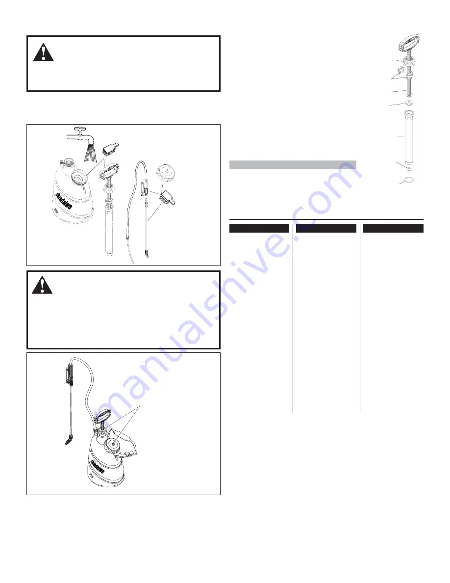
Cleaning the Sprayer

After finishing the spray application, empty the sprayer and
wash all equipment in an approved decontamination area.

Pump Disassembly

Piston

Piston

Cup

Pump

Cylinder

Cylinder

Cap

Piston

Guides

Diaphragm

Valve

O-Ring

Hose seal, cap seal
or pump chamber
o-ring damaged.

Presure relief valve
inopperative.

   WARNING!

Always relieve pressure from the sprayer tank by pulling
the pressure relief valve before removing the tank lid.

Periodically lubricate the pump handle, bushings and tank lid
pressure relief valve with a light-weight machine oil.

Lubricate

with a light-

weight

machine oil.

Summary of Contents for 80555

Page 1: ...P210 SPRAYER Part Number 80555 Rev 7 06 WARNING Minimize the risk of injury to your self and others Read this manual and familiarize yourself with the contents Always wear eye protec tion gloves and a...

Page 2: ...nge without notice Prepare to Assemble Introduction Push the wand into the trigger valve and secure with screw cap Hand tighten to prevent leakage CAUTION Do not overtighten Trigger Valve Wand Screw C...

Page 3: ...m hat Protective mask equipped with appropriate filters Do not eat drink or smoke while handling chemicals or while you are spraying Always handle chemicals in a well ventilated area while wearing app...

Page 4: ...568774 Spray wand assembly 21 6 Plastic handle trigger valve and spray tube 40 mesh stainless steel nozzle and trigger valve filters included Fitted with adjustable cone nozzle Part Number Description...

Page 5: ...e and or leakage at the cylinder After pumping and pressurizing the tank the pump handle rises slowly when released prior to being locked in place Sprayer will not hold pressure Tank lid difficult to...

Page 6: ...6 Illustrated Parts List SP210 1 2 3 4 5 6 7 8 9 10 11 12 13 12 14 15 16 17 18 19 20 21 22 23 24 13 25 26 27 28 29 30 31...

Page 7: ...15744 Screw cap 2 14 336263 Spray tube 1 15 635276 Elbow 1 16 730366 Nozzle filter 40 mesh 1 17 015024 Adjustable cone nozzle 1 18 942193 Screw cap S 20 1 19 048116 Hose dip tube assembly 1 20 285312...

Page 8: ...sequential damages Some states do not allow the exclusion of incidental or consequential damages so these limitations may not apply to you This warranty give you specific legal rights and you may also...

Page 9: ...9 NOTES...

Page 10: ...10 NOTES...

Page 11: ...NOTES...

Page 12: ...n Oregon 97062 Telephone 503 692 3070 Fax 503 692 6696 www shindaiwa com 2006 Shindaiwa Inc Part Number 80555 Revision 7 06 Shindaiwa is a registered trademark of Shindaiwa Inc Specifications subject...

Reviews: