6
BP3511
BP3509
BP3504
BP3510
BP3508
BP3507
BP3506
BP3505
Assembly: Driveshaft/Powerhead
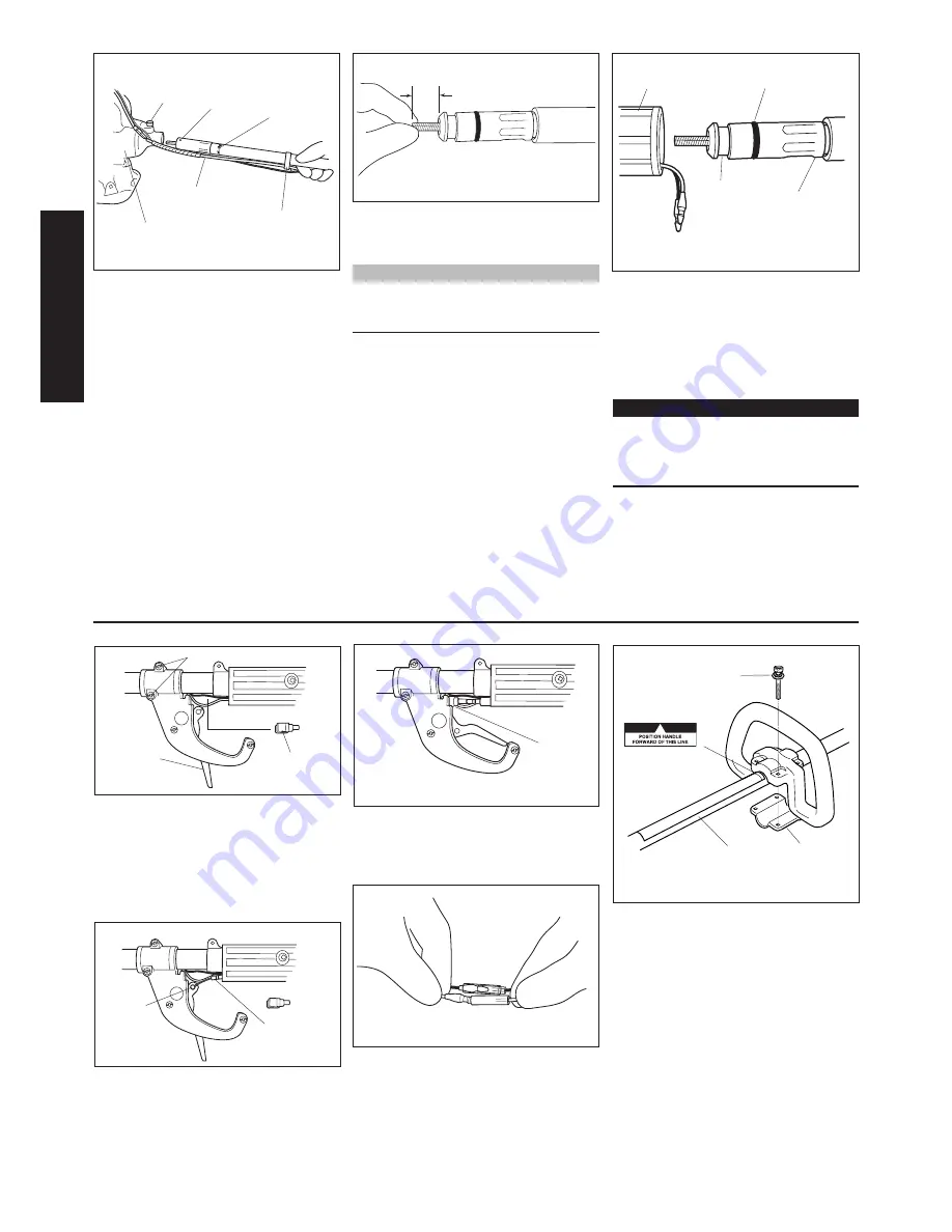
1. Place the powerhead on a flat surface.
2. Route the “engine side” of the flex
cable through the cable holder.
3. Remove the two protective covers
from the flex cable and insert the flex
cable housing marked “engine end”
into the powerhead with the locking
hole facing up. See Figure 4.
4. Lift up on the flex cable release knob
and slide flex cable housing all the
way in until it bottoms in the case and
the release knob locks into the lock-
ing hole in the flex cable housing. See
Figure 5.
BP35 Brushcutter
ASSEMBL
Y
Figure 4
5. From the opposite end, rotate and
push the drive cable to engage it into
the clutch drum. See Figure 5.
NOTE:
No more than 7/8” (22 mm) of the flex
cable should protrude from the flex cable
housing when properly installed.
Figure 5
6. Remove the Phillips head screw
from the rear hand grip and slide the
O-ring end of the flex cable housing
into the rear of the outer tube handle
until the groove on the housing lines
up with the hole for the Phillips head
screw. See Figure 6.
IMPORTANT!
It may be necessary to rotate the
output shaft of the gearcase to fully
engage the drive cable into the lower
tube assembly.
7. Install and tighten the Phillips head
screw firmly.
Figure 6
Release Knob Locking
Hole
“Engine Side”
Label
Throttle Cable
Cable Holder
7/8"
Powerhead
Groove
O-Ring
Rear Handle
Flex Cable
Housing
Throttle and Handle Assembly
Install the Handle
Cable
Guide
Outer Tube
Throttle Cable
Handle Position
Label
Figure 11
Throttle
Lever
Figure 8
Figure 7
Cable
End
Lower
Clamp
Figure 9
1. Use a Phillips head screwdriver to
remove the lower clamp retaining
screws from the handle. Separate the
clamp from the handle.
2. Position the handle on the outer tube
behind the handle positioning label.
Reassemble the lower clamp to the
handle in the reverse order of disas-
sembly. See Figure 11.
3. Firmly tighten the (4) handle retain-
ing screws. See Figure 11.
Install the Throttle Cable
1. Loosen the two screws securing the
throttle assembly and slide it forward
on the outer tube. See Figure 7.
2. Remove the cable guide to allow
the throttle trigger to swing out.
See Figure 7.
3. Slide the throttle cable through the
hand grip and insert the cable end
into the recess in the throttle trigger.
See Figure 8.
4. Install the cable guide and slide
the throttle assembly back into
place. Tighten the screws securely.
See Figure 9.
5. Connect the powerhead and stop
switch wire terminals.
Figure 10
Loosen screws
Cable
Guide
Clamp Retaining
Screw
Summary of Contents for BP35
Page 19: ...19 NOTES ...


