7
Prior to Assembly
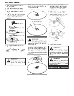
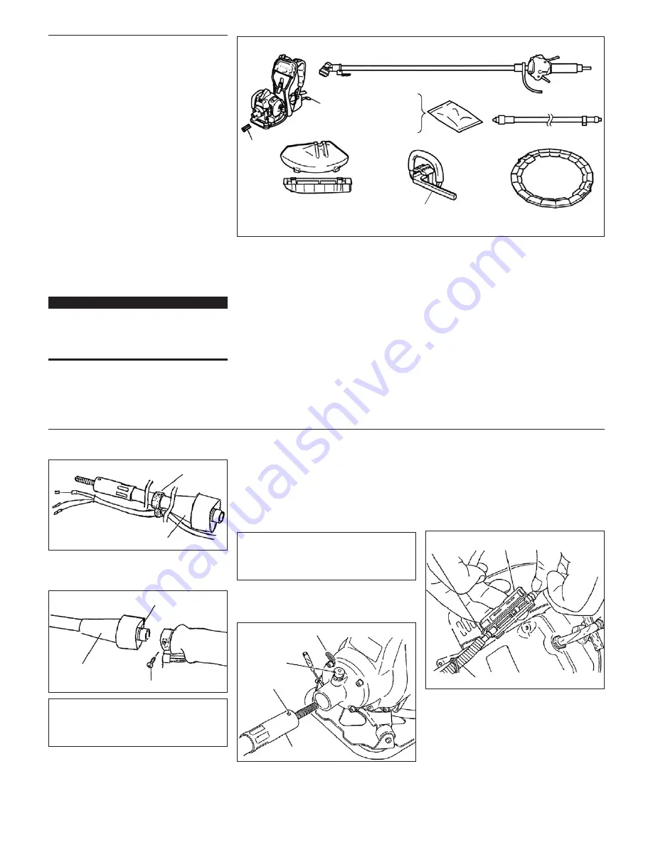
Before assembling, make sure you have all
the components required for a complete
unit:
Engine assembly
Outer tube assembly
Debris shield
Cutting attachment
Loop Handle and Barrier
Blade cover
Tool kit, which includes 4 mm and 5 mm
“L” type hexagonal wrenches, 8 mm/
l0 mm open-end wrench and
combination spark plug/ tool holder
wrench. Tool kits vary by model.
Components required for assembly
(throttle cable connector).
Carefully inspect all components for
damage.
IMPORTANT!
The terms “left”, “left-hand”, and “LH”;
“right”, “right-hand”, and “RH”; “front” and
“rear” refer to directions as viewed by the
operator during normal operation.
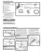
Assembly Procedure
Engine Assembly
Outer Tube Assembly
Harness
Connector
Guard
Barrier
Blade Cover
Flexible Pipe
Handle
Tool Set
Hex Wrench (M5)
Hex Wrench (M6)
Plug Wrench
Spanner Wrench
Assembly of the Flexible Pipe
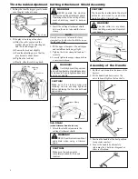
1. Put the flexible pipe through the holder
hole.
CAUTION!
Make sure the inserting direction of the
flexible pipe is correct as shown.
CAUTION!
Pull the flexible pipe and make sure it is
securely locked by the stopper knob.
Holder
Flexible Pipe
2. Loosen the bolt of the outer tube and
insert the O-ring of the flexible pipe into
the outer tube.
O-Ring
Bolt
Flexible Pipe
3. Make sure the groove of the flexible
pipe aligns with the bolt, and then
tighten the bolt. Make sure the flexible
pipe does not come off the outer tube.
4. Insert the other end of the flexible pipe
straight into the engine to the end. (It is
not necessary to pull the stopper knob
when doing this.)
5. Make sure the stopper knob is in the
hole of the flexible pipe and it is securely
locked.
Cable Holder
Stopper Knob
Flexible Pipe
Hole
6. Put the throttle cable (flexible pipe
side) through the cable holder, and
then connect the throttle cables in the
connector as shown.
7. Connect the red wire from the engine
to the white wire from the throttle, and
connect the black wire from the engine
to the black wire from the throttle.
Throttle
Cable
Connector
Cable Holder


