10
5.
Equipment
5-1. Warning Indicators
This generator is equipped with the following warning indicators: CHARGE (battery charge),
OIL PRESS (engine oil pressure), WATER TEMP (coolant temperature), OVER SPEED
(engine overspeed), AIR FILTER (air cleaner clogging), and SPILL CONTAINMENT (spill
containment amount). An indicator lights up if a malfunction/fault occurs during operation
and the engine automatically stops depending on the fault type. Moving the starter switch
from STOP to RUN causes the following indicators to light up for approximately 0.5 sec.:
OIL PRESS, and WATER TEMP.
(1)WATER TEMP (Coolant Temperature) Warning Indicator (High Water Temp.)
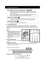
CAUTION: BURNS
Do not open the radiator cap immediately after stopping the engine.
Do so will result in hot steam gushing out.
Hot steam gushes out from the coolant sub-tank if the generator overheats. Do
not touch the coolant sub-tank.
If the coolant temperature rises above 110
℃
℃
℃
℃
during operation, the WATER TEMP and
ENGINE warning indicators light up, and the engine automatically stops. If this occurs, hot
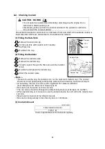
steam will gush out of the coolant sub-tank. Check the coolant sub-tank coolant level after
the generator cools and add coolant to the coolant sub-tank if it is insufficient. (Refer to
section “
8-2. Checking Coolant
”.) If the coolant is at the specified amount, it is probable
that the fan belt is loose or there is a coolant leak. Wait for the engine to cool and inspect
for these problems.
< Note>
The coolant temperature cannot be detected if the coolant level is excessively low. Always be
sure to check the coolant level in the radiator coolant sub-tank before starting work.
WARNING : INJURY
Close all doors and place locks during operation, to avoid injuries by
unintentionally contact with moving parts such as the cooling fan and fan belt.
Before performing any equipment check or maintenance, stop the engine, and
remove the engine key. A person performing the maintenance should always
keep the key.
CAUTION : BURNS
Do not touch the engine and surrounding components immediately after
stopping the equipment, while temperature can reach extremely high.
Summary of Contents for DG50MK-P
Page 2: ......
Page 43: ...40 13 Generator Circuit Diagram...
Page 44: ...41 14 Engine Electrical Circuit Diagram...
Page 45: ...42...
Page 46: ...43...
Page 47: ...44...
Page 48: ...2016...


