17
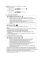
Expedient Formula: the voltage drop of cables
3-Phase 3-Wire
1-Phase 2-Wire
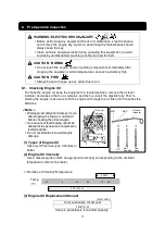
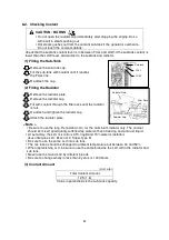
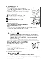
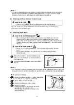
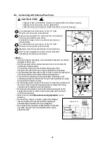
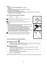
7-2. Connecting Load Cables
WARNING : ELECTRIC SHOCK
Before connecting or disconnecting the load cables to/from the output
terminal, always turn the output circuit breakers to the OFF position, stop the
engine, and remove the engine key.
The person performing the maintenance should always keep the key.
Close the output terminal cover before operating.
Do not touch the generator if the Aiternator or casing becomes wet during
operation.
CAUTION : FIRE
Do not connect the generator output to indoor wiring.
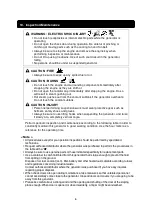
< Note >
Divide loads into 3 circuits proportionally as possible, when using the maximum output power
especially, and connect them to each phase (R,S,T) respectively.
Be careful to limit the current under the rated current per the phase.
Note that the 1-phase output power decreases when 3-phase output power is used
simultaneously.
Be careful to limit the total current under the rated output current when using 1-Phase and
3-Phase output simultaneously.
7-3.
Earth Leakage Relay and Grounding
WARNING : ELECTRIC SHOCK
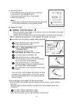
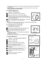
Ground the every grounding terminal to the earth as set in the manual.
If even one of all is unconnected by mistake or accident, it will be
much more dangerous for human than the NO-RELAY case,
because leaking current inevitably goes through the body.
Even though all the bonnets of the loads have been grounded to the earth,
the bonnet grounding terminal should be grounded to the earth.
Grounding should be made after the engine is stopped.
Whenever the Earth leakage breaker is activated, you should always repair
the leaking place first of all.
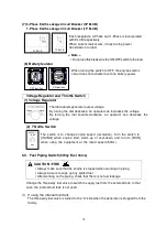
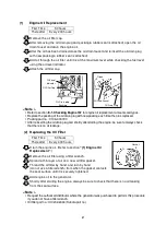
The generator is provided with the earth leakage breaker relay to detect any leakage
produced due to such the trouble as insulation failure of the load while the generator is
running and to cut off the circuit for protection against any accident such as electrical shock
resulting from the trouble.The specification of the earth leakage relay ;
Rated Sensitive Current: 30mA (or below) (Grounding resistance: 500
Ω
or below)
Sensitive time: Within 0.1 second.
2
(A)
Current
(mm
Dia
(m)
Length
58
1
(V)
Drop
Voltage
2
×
×
×
=
)
3
(A)
Current
(mm
Dia
(m)
Length
58
1
(V)
Drop
Voltage
2
×
×
×
=
)
Summary of Contents for DG50MK-P
Page 2: ......
Page 43: ...40 13 Generator Circuit Diagram...
Page 44: ...41 14 Engine Electrical Circuit Diagram...
Page 45: ...42...
Page 46: ...43...
Page 47: ...44...
Page 48: ...2016...


