35
(10) Elimination of carbon in the exhaust pipe line and muffler
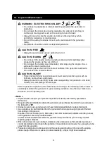
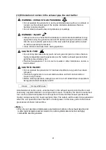
WARNING : EXHAUST GAS POISONING
Do not operate the generator in poorly ventilated areas such as an indoors or
tunnels, as the exhaust gas of the engine contains substances that are
harmful to human health.
Do not direct exhaust fumes at bystanders or buildings.
WARNING : INJURY
Always be sure to check that the breakers on load side and switches for any
equipment using the generator are at OFF before turning the breaker to ON.
Also be sure to advise personnel on the load side that power will be turned
on before operating the breaker.
Close all doors and lock them during operation.
CAUTION : FIRE
Do not bring flammable items (such as fuel, gas and paint) or items that are
highly combustible near the generator as the muffler, exhaust gas and other
parts become extremely hot.
Position this generator 1 m or more from walls or other hindrances, and on a
level surface.
CAUTION : INJURY
Do not operate the generator if it has been modified or any parts have been
removed.
Position the generator on a level stable surface so that it cannot slide or
move in any manner.
Before starting operation, always be sure to turn off all switches of equipment
being used and all breakers to OFF.
Clean
Every 200 hours
Accumulation of carbon (soot, unburned fuel) in the exhaust pipe line and muffler could
cause only a system derates or an engine fault occurs. To destroy the soot and unburned
fuel, run the unit at rated power for some period of time until the exhaust gas become
mostly colorless every 200 hours operation time. The carbon will be easier to be generated
when the unit operates at less than 30% of rated power. In this case, perform the above
procedures at shorter interval time.
< Note >
When the unit operates at rated power, accumulation of carbon in the exhaust pipe line and
muffler might be lead to back fire incident. Do not bring flammable items that are highly
combustible near the generator.
Summary of Contents for DG50MK-P
Page 2: ......
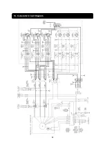
Page 43: ...40 13 Generator Circuit Diagram...
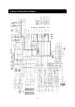
Page 44: ...41 14 Engine Electrical Circuit Diagram...
Page 45: ...42...
Page 46: ...43...
Page 47: ...44...
Page 48: ...2016...

