background image


2.


Specifications 

2-1.  Specifications 

Model 

Unit


DG50MK-P/ANZ 

A

lt

e

rn

a

to

Generating Type 

Rotating Field, Brushless 3-Phase 

Synchronous Alternator 

Rated Output 

kVA 

50 

kW


40


Rated Voltage 

415 

Rated Current 

69.6 

Rated Frequency 

Hz 

50 

Winding 

3-Phase, 4-Wire 

Power factor 

80 

Insulation class 

Excitation 

Self-Excitation(Brushless) 

No. of poles 

E

n

g

in

e


Types 

Vertical Water-Cooled 4-Cycle Diesel Engine 

Model (Manufacturer) 

V3800DI-TI (KUBOTA) 

No. of Cylinders (bore x stroke) 

mm 

4 (100 X 120) 

Continuous rated output 

kW 

49.2 

PS


66.9 

Rated speed


min

-1


1500 

Displacement 

3.769 

Combustion system 

Direct Fuel Injection with Turbo Charger 

Cooling method 

Radiator 

Lubricating method 

Forced Lubrication 

Starting method 

Electric Start 

Fuel 

Diesel Fuel 

ASTM No. 2-D


Lubricant oil 

CD class 

Fuel tank capacity 

420 

Lubricant volume (Full) 

13.2 

Cooling water volume 

12.5 

Starting motor capacity 

V-kW 

12 - 3.0 

Charging dynamo capacity 

V-A 

12 - 80 

Battery   

130E41R 

U

n

it


Length 

mm 

1970 

Width 

mm 

880 

Height 

mm 

1665 

Dry Weight 

kg 

1315 

Installed Weight 

kg 

1705 

Summary of Contents for DG50MK-P

Page 1: ...Vertical Water Cooled 4 Cycle Diesel Engine DG50MK P X750 026 44 1 X750802 130 1 CAUTION Do not operate the Generator or any other appliance before you have read and understood the instructions for us...

Page 2: ......

Page 3: ...ration Store this manual in a specified location where it will be secure and available for consulting at any time Order another copy from the authorized distributor where this generator was purchased...

Page 4: ...ion 16 7 2 Connecting Load Cables 17 7 3 Earth Leakage Relay and Grounding 17 8 Pre Operation Inspection 19 8 1 Checking Engine Oil 19 8 2 Checking Coolant 20 8 3 Checking the Fan Belt 21 8 4 Checking...

Page 5: ...the body Even though all the earth terminals of the loads have been grounded to the earth the bonnet grounding terminal should be grounded to the earth There is always a danger of being electrocuted b...

Page 6: ...ny spilled fuel or oil Allow the generator to cool before covering with the protective cover Never allow flame to come close to the generator CAUTION BURNS Do not touch the engine and surrounding comp...

Page 7: ...or thin resulting in decreased input voltage to equipment using the generator thereby causing decreased performance faulty operation and malfunction Warning Caution Label Locations If warning or cauti...

Page 8: ...rer V3800DI TI KUBOTA No of Cylinders bore x stroke mm 4 100 X 120 Continuous rated output kW 49 2 PS 66 9 Rated speed min 1 1500 Displacement L 3 769 Combustion system Direct Fuel Injection with Turb...

Page 9: ...Ambient temperature 15 to 40 degree Celsius Relative humidity 80 or less Elevation 300 m or less 3 Applications Power source for submerged pumps and similar civil engineering equipment Power source f...

Page 10: ...Oil Level Indicator Oil Filter Oil Filler Coolant Drain plug Oil Drain plug 3way fuel valve External Tank Fuel Return External Tank Fuel Inlet Water Separator Fuel Filter Battery Alternator Check Doo...

Page 11: ...ter Starter Switch Ammeter Voltmeter Selector Switch Frequency Meter Ammeter Selector Switch Water Temperature Gauge Voltage Regulator Fuel Gauge Throttle Switch Hour Meter Panel Light Switch Pilot La...

Page 12: ...e Breaker 32A 3 Phase ELCB 1 Phase ELCB 1 Phase Receptacle 15A 3 Phase Receptacle 32A 3 Phase Receptacle 20A 3 Phase Breaker 20A 1 Phase Breaker 15A 3 Phase Breaker 50A 3 Phase Receptacle 50A 4 3 Outp...

Page 13: ...TEMP and ENGINE warning indicators light up and the engine automatically stops If this occurs hot steam will gush out of the coolant sub tank Check the coolant sub tank coolant level after the generat...

Page 14: ...possible and the battery voltage drops below 8 V the ENGINE warning indicator also lights up and the engine automatically stops If this occurs contact the authorized distributor where the generator w...

Page 15: ...illed up it shows F When the hand is approaching to E the volume is coming to empty Replenish fuel enough promptly Generator Meters and Gauges 1 Voltmeter Voltmeter displays the output voltage Phase t...

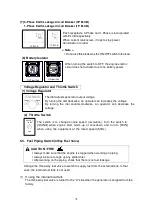
Page 16: ...y Stop Button This button is used to stop the engine in emergency By inserting the button the engine stops Be sure to restore the starter switch to STOP and re set the button turning clockwise after u...

Page 17: ...turning the dial counter clockwise an operator can decrease the voltage 2 Throttle Switch The switch is to change engine speed revolution Turn the switch to IDLING when engine start warm up or cool d...

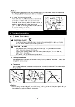
Page 18: ...ling No persons should be under a lifted generator CAUTION INJURY Always be sure to use lifting hooks when lifting up the generator and raise it slowly at a completely vertical angle Personnel perform...

Page 19: ...heck doors are accessible for internal inspection maintenance Note This equipment must be operated on hard and flat surface Operating under any other conditions may result in malfunctions Do not block...

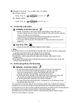
Page 20: ...and 3 Phase output simultaneously 7 3 Earth Leakage Relay and Grounding WARNING ELECTRIC SHOCK Ground the every grounding terminal to the earth as set in the manual If even one of all is unconnected b...

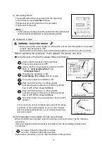
Page 21: ...9 1 Initial Starup Pre Check start an engine Turn every breaker and ELCB to ON Push the TEST button on 3 Phase ELCB Indicator changes to Green from RED and ELCB trips to OFF Which shows NORMAL Push t...

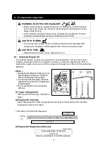
Page 22: ...ins and then re insert the dipstick fully Prior to starting the engine make sure to fill the engine oil through the oil filler until it reaches the MAX line Note Wait approximately five minutes or mor...

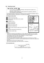
Page 23: ...or is full Re attach and tighten the radiator cap Attach the radiator plate Note Be sure to use the long life coolant LLC for the aluminium radiator only The coolant should be mixed good quality softe...

Page 24: ...ure to stop the engine and not bring flames close when inspecting fuel or refueling Wait until the engine has cooled before performing such procedures If fuel spills always be sure to open the spill c...

Page 25: ...to receive medical treatment especially if the fluid contacts the eyes CAUTION EXPLOSION Never use or recharge the battery if the fluid level is below the minimum level Do not create sparks or bring f...

Page 26: ...able surface so that it cannot slide or move in any manner Before starting operation always be sure to turn off all switches of equipment being used and all breakers to OFF Note Check that the surroun...

Page 27: ...orless or slightly bluish Note If abnormal stop using this generator and request authorized distributor where the generator was purchased to repair the generator 2 Adjustment during Operation During l...

Page 28: ...on by use of indicator lamps Check the fault location when the engine is automatically stopped or an indicator lamp lights up to stop the engine Protection Feature List No Action Abnormality ELCB Trip...

Page 29: ...lower than this generator will result in poor engine operation or stoppage Turn the 3way fuel valve lever to the A side in order to prevent fuel from flowing out from the external tank fuel inlet retu...

Page 30: ...y at a completely vertical angle Perform periodic inspection and maintenance according to the following table in order to constantly maintain this generator in good working condition Use the hour mete...

Page 31: ...Water separator and Gauze filter Clean Fuel tank Clean Check for leaks Fuel Oil Coolant Fuel Cooling Water Oil Hoses and Anti Vibration Rubber Replace Air cleaner element Clean Replace Clean Replace B...

Page 32: ...drain plug and shortly after starting the engine be sure to always check that there is no oil leakage 2 Replacing the Oil Filter First Time 50 hours Thereafter Every 400 hours Drain the engine oil Ref...

Page 33: ...1 Kubota part no Cleaning the air filter element If dry dust is adhering Blow compressed air from inside the element If carbon or oil is adhering Replace with new parts 4 Draining Water from the Water...

Page 34: ...s Remove the fuel drain plug and packing with rubber seal After the water has been drained reinsert the fuel drain plug with new packing with rubber seal Note Replace the packing of the fuel drain plu...

Page 35: ...t can accumulate in the spill containment include oil fuel coolant water and battery fluid such that it is not possible to distinguish between rain water and other liquids Dispose of flushed liquids a...

Page 36: ...e Note After reassembling bleed air from the fuel system Refer to section 9 2 Procedures during Operation After reassembling check that there is no fuel leakage Spill Containment Cleaning Inspection U...

Page 37: ...34 Bolt Wire Connector Washer Washer Bolt Fuel Line Inlet Side Lifting Hook Fuel Tank Spill Containment Fuel Line Return Side Wire Connector Inlet Port Return Port...

Page 38: ...from walls or other hindrances and on a level surface CAUTION INJURY Do not operate the generator if it has been modified or any parts have been removed Position the generator on a level stable surfac...

Page 39: ...lled fuel or oil Allow the generator to cool before covering with the protective cover CAUTION BURNS Do not touch the engine and surrounding components immediately after stopping the equipment while t...

Page 40: ...this generator between each generator and set another generator on top of the ties Never stack more than two levels and do not set a generator on top that is larger in weight size than that on the bo...

Page 41: ...lter 4 Drain water in water separator fuel filter or fuel tank 5 Extract the air 6 Check piping connection 7 Check lever 3 way valve 8 1 Check Change fuse 8 2 Check Change fuel cut Ambient temperature...

Page 42: ...e 3 Disconnected circuit loose terminal or departed 4 Initial exciter is defective 5 Alternator is defective 6 AVR protective device operation 1 Ask our distributor to repair 2 Ask our distributor to...

Page 43: ...40 13 Generator Circuit Diagram...

Page 44: ...41 14 Engine Electrical Circuit Diagram...

Page 45: ...42...

Page 46: ...43...

Page 47: ...44...

Page 48: ...2016...

Reviews: